Windpower king looks to be Oklahoma
Notice the land area in MA is almost same as TX!
(explanation is probably large offshore wind farms
in MA.)
source --- http://www.nrel.gov/docs/fy08osti/42794.pdf
Overview
50% efficiency mystery
Introduction
Theory
Principle
of operation
Wind
power equation
Theoretical
wind turbine efficiency analysis is sketchy
Betz
limit
Betz
limit decoded
Understanding
the Betz results -- my Wikipedia edit
Betz
model applied to modern turbines
Wind turbines
2.5
Mw Clipper (USA)
Nordex
2.5 Mw electrical specs (German)
Direct drive wind turbines
2.3
Mw Enercon gearless (German)
Notes
on Enercon patents
E-126
7 Mw world's largest wind turbine
Enercon
2.0 Mw gearless spec
Siemens
3 Mw direct drive wind turbine (SWT-3.0-101)
Northern
Power 2.3 Mw direct drive turbine
Wind turbines (cont)
2.1
Mw from India (Suzlon)
3
Mw Acciona (Spanish design)
Cape
Wind ---Offshore wind farm on Cape Cod
Deepwater
wind --- wind turbines off the coast of Block Island RI
Alstom 6 MW turbine -- (French/Spanish)
offshore turbine
GE
3.6 Mw (offshore) wind turbine (cancelled)
GE
Wind 2.5 Mw turbine (USA, formerly Zond/Kenetech)
Kenersys
2.5 Mw turbine model K100
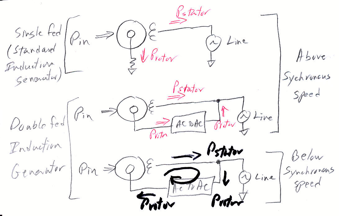
Types of generators
Double-fed
induction generator
How
a double fed induction generator works in sketches
PM
generators
Electronics
High
capacity IGBT's
Cost
comparison to 1,000 Mw nuclear plant
Wind turbine manufacturers
Wind turbine history
1.5
Mw Chinese turbine goes up near Boston
Blade characteristics
Blade
as airfoil
How
blade 'airfoil' is driven forward
Blade
lift and rotation
How
is the lift of a wind turbine blade different from an airplane wing?
Turbine
blade view
Explaining
the shape of the blade
Blade
numbers from 1999 Bonus Turbine paper
Alternate wind turbine designs
Vertical
wind turbines
Savonius
(vertical, drag) wind turbines
Darrieus
(vertical, lift) wind turbines
Makani
Flying Wing turbine
Appendices
Astralux
Ltd --- a wind turbine scam
Detailed
spec of 5 Mw offshore wind turbine
P51
airplane propeller
Misc
wind turbine (old stuff)
References
4 m/s = 9 mph
min speed (cut-in)
10 m/s = 22 mph
midband speed (75 - 80% rated power)
12.5 m/s = 28 mph
rated power speed (100% power 12.5 to 25 m/sec)
25 m/s = 56 mph
turbine stop (> 25 m/s)
70 m/s = 156 mph
survivable (storm) wind
Turbine wind bands (above) are nearly independent of the turbine power rating. Power scaling is done by varying the size of the turbine: power going up as the radius squared, and the rotation period decreases as 1/radius. A large 2.5 Mw wind turbine has a radius of about 45m, a period of about 3 seconds, and is almost 50% efficient mid-band.
Competing on cost (update 11/24/14)
A story in
the NYT today indicates that wind (and solar too) is beginning to achieve
a long sought goal, at least in the midwest and south where is lots of
wind. Utilities report these alternative energy sources in these regions
are successfully competing on price with fossil fuels (even gas) without
subsidies.
This is the result of years of hard won engineering, nurtured by subsidies,
to produce a competitive reliable energy product as I have documented in
this essay. The NYT story gives these costs being paid by utilities for
future contracts to buy power (power purchase agreements): natural gas
6.1 cents/kwh (baseline) and coal 6.6 cents/kwh (baseline). Without subsidies
wind is as low as 3.7 cents and solar 7.2 cents; with subsidies wind is
1.4 cents/kwh and solar 5.6 cents/kwh.
Overview
Modern wind
power turbines are physically huge with (peak) outputs in the low Mw range.
Towers are about as tall as 25 story buildings and blade dia is larger
than a football field. Modern large turbines incorporate two engineering
advances over older sub-Mw turbines that have increased wind capture efficiency:
variable blade speed (made possible by IGBT electronics) and variable blade
pitch (older turbines relied on blade stall to limit power capture in high
speed winds).
Each large wind turbine is a mass produced equivalent to 1/1,000th (roughly) of a standard 1,000 Mw power plant They cost about x1.3 more than a conventional coal plant making them (with a 30% subsidy) roughly cost competitive. They are now far more cost competitive than solar. Wind power is on track to grow to provide about 20% of the country's electric power in 20 years (2030), or 200 Gw from about 200,000 turbines. At 5 million dollars/turbine this is an investment of one trillion dollars, equivalent to 10,000 dollars/household (assuming 100 million households in USA).
Will drastically lower natural gas prices kill off wind? (4/12)The current state of the art in wind turbines (onshore) is 2.5 Mw, though the installed base is mostly 660 kw to 1.5 Mw. The 2.5 Mw limit is primarily set by what is movable by truck. For offshore or riparian (where movement is by ship) the state of the art is somewhat larger, 3.6 Mw to 7.5 Mw, basically scaled up 2.5 Mw's. Wind turbines like solar are rated at peak power. The average power from a wind turbine (at a good site) is about 30% of peak, so a 2.5 Mw wind turbine average power output is 0.75 Mw. At 0.75 Mw per wind turbine it takes 1,333 wind turbines to put out the same power as a standard 1,000 Mw (nuclear or coal) baseload power plant!
In a recent article in Slate there is a brief mention of the effect of drastically lower lower natural gas prices on economics of wind turbines. The technical revolution of horizontal drilling combined with rock fracturing has caused US natural gas prices in the last four years to drop from $10 to $2. There is direct competition between energy sources in planning for electrical plants, so a x5 reduction in gas prices (if sustained) is huge. Gas plants are easy to build, don't need a lot of space or capital, but my understanding is a big gas plant does require a direct pipeline to gas wells."Boone Pickens, once of the wind sectors biggest boosters, says wind projects need $6 natural gas to be competitive. Pickens also recently said Ive lost my ass in the wind business." (Slate --- Obamas Oil Blindness, by Robert Bryce, April 25, 2012)This smells like what happened in the years after the 1970's oil embargo when oil prices came way down and killed off the developing technologies of alternate energies. What congress should have done years ago is to put a floor, using taxes, under oil and gas prices that would keep alternate energies, like wind, viable. Instead it's being done with 'mandates', which are political and easily reversed when a new party comes to power.
Large 2.5 Mw wind turbines from different manuf are very similar, similar specs and in pictures they look almost the same. They have three thin (fiberglass/epoxy) blades, sweep out about 90 m dia (football field!), variable speed, variable pitch, actively pointed into the wind, on a tall (unguyed) steel tower (80 m). Two types of generators are in use (PM and double-fed asynchronous), and there is some variation in gear box design. One large wind turbine maker (Enercon) has long used no gearbox, instead coupling the blades directly to a very high torque, low speed generator. Northern Power, a maker of small (100 kw) direct drive turbines, has just introduced (2011) a large 2.3 Mw turbine also with no gearbox, and GE has one in development.
2.5 Mw wind turbines need about 10 m/s wind (22 mph) to output 2 Mw power. Amazingly (in the center of the power range) large wind turbines can capture about 50% of the energy in the wind that exists in an (imaginary) cylinder extending forward from the blades! Winds above 12.5 m/s (28 mph) have (far) more energy than the blades and electronics can handle, so from 12.5 m/sec (28 mph) and 25 m/sec (56 mph) the blades are slowly pitched (featured) to hold the turbine power at its rated power level.
The bigger the turbine the slower the rotation rate. The rotation period for Mw turbines is in the 3 to 6 sec range. In the center of the power range (wind speed 4 m/s to 10 m/s) the speed of the blades is controlled to increase linearly with the wind speed. The blade tip ratio (blade tip velocity to wind velocity) is controlled to be about 7 to give a high, stable angle of attack which results in good efficiency. This is why large turbines rotate slower. A larger radius for a specific m/sec air speed at the blade tip means a lower angular rotation rate (rad/sec).
Cut-in speed is 3 to 4 m/s and at about 12.5 m/s power hits max. In the upper half of the wind speed range (12.5 m/s to 25 m/s) the wind turbine runs at maximum power, shedding up to 90% of the available wind power at 25 m/s by adjusting the blade pitch and not allowing the rotation rate to increase. Above 25 m/s (56 mph) the wind turbines go off line with the blades feathered (80-90 degrees) for zero rotational force and brake locked. A fairly common survivable speed is 59.5 m/s (133 mph). Below cut-in wind speed, say 3 m/sec, no power is sent to the grid, but a small amount of power is generated by the blades, and it is used to accelerate the mass of the blades up to the minimum operational speed [3 m/sec (wind) x 7 (tip speed ratio) = 21 m/sec (tip speed)].
Enercon -- large wind turbines that are different50% efficiency mystery
For a long time the one exception to the similar large wind turbine rule were those made by Enercon (Germany). Their turbines have no gearbox. Instead they bolt directly to the blades a super high torque (> million ft-lbs!), very large dia ring shaped generator. Their turbines have a wider speed range (> 3:1) than others and results in higher efficiency (50%) over a wider range of mid-band speeds.Enercon is the largest wind turbine manuf in Germany (3rd world wide). They have been able to scale up their direct drive (gearless) design to a real monster, 7.5 Mw with 126 m dia rotor on a 42 story concrete tower that is now in production.
Power =
torque x angular speed
=
[radius x force] x angular speed
= [radius x (forward component of lift force)] x
blade rotation speed (in rad/sec)
While this may be satisfying to an aerodynamicist and (clearly) it provides accurate predictions of performance, it does not provide any intuitive explanation of how wind turbines really works. There is no (ground based) picture of how the air flows, of how it transfers so much of its wind kinetic energy to the occasional blade that slices through perpendicularly. Since the incoming wind loses half its wind kinetic energy to the blades, the air stream must be getting slowed down by the blades, but how exactly? The blade circle is 90-95% open, the air is coming by fast (10 m/sec, 33 ft/sec midband) and a narrow blade slices through about once a second, so why doesn't most of the air just pass through the blade circle without ever coming near a blade? I have searched and searched, emailed experts (one replied, "that's a good question"), and (as of Dec 2011) have found no answers.
The few papers on efficiency (not 'capacity' with which it is often confused) I find generally discuss the nearly century old Betz limit, which makes so many simplifying assumptions that I question how relevant it is to commercial wind turbines (see below). The widely quoted Betz limit of 59.3% provides only a crude limit as it is a very simplified one dimensional model constructed in the pre-computer era to be easily solvable. A recent paper that updates the Betz analysis by including radial flow terms calculates an efficiency of only 30%, which is clearly too low as this is far exceeded by real turbines.
Revised view of Betz modelEnergy payback time (update 6/14/11)
After spending considerable time to gain an understanding of the Betz flow model, I suspect it probably does provide a reasonably accurate picture of how the approaching air (assumed incompressible) flows through and around the blade area. It does not, however, provide any guidance at all about how the air flow interacts with the three turbine blades, because the betz model is bladeless. The Betz model just assumes a uniform pressure drop across (and near) the blade circle.Some references say the cause of the pressure drop in the Betz model can be thought of as being caused by a semi-permeable membrane (or series of membranes) that has resistance to flow. [Power = force x velocity], so flow forced though a resisting material would lose energy in the form of heat to the membrane(s). In fact the simple mathematical derivation in Wikipedia (Betz Limit) just shows a milk bottle shaped flow that widen as it slows. In the model a slowing flow is assumed, which implies energy is being lost, but the model and equations have no mechanism (zero, nada) to explain what causes the slow down or where the energy goes.
In real wind turbines power flows out of the generator, so the wind must be doing work (in physics 'work' is energy and is measured in joules) on the blades. If the Betz model applies to real wind turbines, which I think now it probably does, then the blades are probably making rotating pressure waves, which when averaged give the (simplified) uniform pressure drop the Betz model assumes.
A recent op-ed in the NYT (Gas Is Greener, by Robert, Bryce, 6/7/11) compared the amount of steel in wind turbines to gas turbine generators, saying it takes 200 tons of steel to build a 3-4 Mw wind turbine (or 50 tons/Mw), whereas a natural gas turbine built with 9 tons of steel will generate 43 Mw (or 1/4 ton/Mw). In other words a wind turbine he says requires x200 times more steel per Mw than gas turbine generators. He did not, however, not give the energy cost of the steel or the energy payback time.
A letter writer, who is writing a book to be called 'Harvest the Wind', responded that the energy payback time for wind turbines is only 7 months, saying "Wind turbines recover their full life-cycle energy inputs within the first seven months of operation". If true, this is good news. He also pointed out that Bryce did not count the steel required to build the pipelines to transport the gas. I did a little research to try and check this figure, clearly a good starting point would be to find the energy required to make a ton of steel. On my first search I found a confirmation. A steel industry webpage says a 3 Mw wind turbine in 20 years will output x80 times more energy than is used for its production and maintenance, referencing the Danish wind industry association (www.windpower.org). So the wind industry claims a very short energy payback time of only 3 months!
Check --- crude total payback time calculationWind's Future (my views, 2009)
Assume 2.5 Mw turbine, cost 5 million, 30% capacity (good site), and producer gets 10 cent/kwh (high). These are all optimistic numbers. (A 1.5 Mw Chinesee turbine that went up near boston cost 4.7 million.)2,500 kw x 0.30 capacity x 8,766 hr/yr x 0.10 dollar/kw = 657k/yr gross revenue (13.1% of cost)
Total payback time is 7.5 yr (not considering costs), more realistically probably something like 12-15 years and maybe 20 years with less optimistic numbers (sans subsidies).
The goal of the wind industry (in most countries) is to grow to the point that it is supplying 20% to 30% of a country's electricity 10 to 20 years from now. USA goal is 20% by 2030 (http://www.20percentwind.org/). It looks doable. (Denmark has already reached 20% and Germany 8%.) To achieve this annual installations need only grow by x2 or x3 from current levels. The economics are also not that bad, probably a continuing (or declining) subsidy of 1/3rd of the cost, or put another way electricity from wind costs maybe x1.5 times more. That's pretty good for good clean renewable power, and far cheaper than solar.
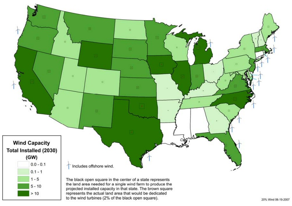
Here's a projection of the amount of land needed by wind turbine farms in each state in 2030 to meet the 20% of electricity goal. 18% of the country's wind power capacity is expected to be offshore, mostly on the east coast, where there is good wind and transmission costs are low, because the power is generated close to where it is needed.
Windpower king looks to be Oklahoma
Notice the land area in MA is almost same as TX!
(explanation is probably large offshore wind farms
in MA.)
source --- http://www.nrel.gov/docs/fy08osti/42794.pdf
Solar engineering is ten or twenty years behind wind. Thermal solar is still in the early prototype and small scale engineering stage and has not settled on architectures for production. Solar cells are further advanced than thermal solar and are at small/medium scale production, but costs remain far too high for full scale production.
(update Dec 2011)Whether there are enough good wind sites to support the tens of thousands of turbines that need to be installed, I have no idea. I see virtually nothing written about this in the general press. (Could be this is wind's dirty little secret?) A study by US Dept of energy shows that a good part of the midwest from Minn down to Texas has pretty good winds and a long strip of high wind sites runs down the Atlantic coast.
Reports are that silicon solar cells have declined greatly in price in the last couple of years, partly due to high Chinese production. I read (hard to believe) claims of a 90% cost reduction in the raw silicon cells.
2.5 Mw wind turbine cost
Turbine manufacturers
appear to sell 2.5 mw turbines for 3.0 to 4.1 million. [Clipper in 2008
sold 248 2.5 Mw turbines for 737 million, which is 3.0 million per turbine.
Another turbine manuf was paid 4.1 million per turbine.] [In 2008 T. Boone
Picken was reported paying GE 3 million each for 667 1.5 Mw turbines he
ordered.]
Cost installed can run 6 million for a 2.5 Mw turbine. Added costs include transportation, which I read can come to 20% of cost, plus installation (tower footing + crane to assemble turbine) and overhead. 6 million per 2.5 Mw turbine scales to about 8 billion for 1,000 Mw baseload plant equiv (1,333 turbines).
Hidden wind (& solar) cost (update 11/10)Introduction
It's slowly being recognized that there is a hidden cost associated with having a lot of wind power that is rarely mentioned in policy discussions. "At current penetration levels in California and parts of Europe have required substantial numbers of new gas power plants to fill in when the wind isn't blowing -- a cost which is typically not counted against the renewables." (From a long Slate discussion of climate and energy policy, Nov 18, 2010)While wind power can greatly reduce the amount of gas burned by these supplemental gas plants, it also means that a lot of capital is needed for plants with high peak power, but low average power.
One, I read that wind power costs have come down to the point where they are nearly cost competitive with fossil fuels. If this is really true it could be a real breakthrough, but is it true? Or does cost competitive mean cost competitive only when taxpayer subsidies are included? [Well, it's the latter of course!]
Second, I saw a picture of men standing on top of a wind turbine and from this perspective I realized how truly enormous wind turbines have become.
Third, I saw a TV show about the adventures of a fleet of trucks hauling monster loads up to South Dakota, which I later realized were a blade and tower segments of a huge wind turbine, I also read (in the New Yorker I think) about a small Texas town in oil country that has become one of the wind centers in the US with wind farms all around the town and wind offices downtown. [Roscoe Wind Farm in Roscoe, Texas is the world's largest wind farm (as of October 2009) with 627 wind turbines and a total installed capacity of 781.5 Mw, and nearby is Horse Hollow farm in TX with an additional 735.5 Mw.]
Fourth, as a motor control and power engineer I'm interested in the electrical technology. In the very early days of wind (early 1980's) as part of my job I read some papers about wind electronics, but nothing since. In the early days the few wind researchers around were exploring how to best couple power from a blade driven wind turbine to the electrical grid. This is a non-trivial problem, and one of the two or three core technologies of a wind turbine. It is tricky because the blade frequency is variable while the line frequency is fixed, and also the power levels vary widely. At the time this was an unsolved problem, but looking at the hundreds of big wind turbines now installed, it is clear one (or more) solutions to the electrical problem have been found. How is it being done I wondered?
Not baseload power
Power is power,
but wind along with solar has a big disadvantage in that its variable and
worse it's not predictable. The power comes and goes (with the wind!).
Some degree of averaging might be possible with many wind farms spread
out across a state, but I have not seen any info on how significant this
might be. Unless some local storage technology is developed (liked pumped
air underground) wind will be a supplemental power source to baseload plants
like coal, nuclear and hydroelectric. Denmark and northern Germany now
generate 20% of their electricity from wind, so intermittency at 20% penetration
is clearly manageable.
[wind turbines + gas plants]Capacity
There are reports that wind power is being paired up with new gas plants designed for high peak to continuous duty. To smooth out the variable wind power what is needed is a power plant that is fast responding, requires the minimum of capital to build, and relatively high fuel costs can be tolerated. Apparently specially designed gas plants serve this need. (A NYT oped pointed out they require x200 less steel/Mw than wind turbines.)It is an interesting to think in terms of [wind turbines + gas plants] as baseload (continuous power) power plants. Politically it's obvious why this barely gets mentioned. Wind looks a lot less 'green' when it is admitted that it needs to be paired up with fossil fuel burning plants to be a reliable source of electrical power!
For comparison the capacity of solar in the southwestern desert is about 25%, meaning the it runs equivalently at full power six hours a day. Univ of MA says solar capacity in Massachusetts is 12% to 15%, or about half of what it would be in a southwestern desert. The lower value in MA is due to clouds and lower angle of the sun in the sky compared to AZ. The capacity of nuclear plants is 92% (national average).
Power vs wind speed
[Power =
torque x speed] with the torque load on fan blades going as the square
of speed. This means the power of the wind increases very strongly (as
the cube!) with wind speed. This basic character of wind power is extremely
important. It means there is a very big payoff to getting the high (steady)
wind speeds. The only practical siting for grid power wind farms is in
the most windy locations and on high towers.
For large turbines (2.5 Mw and up) a good rule of thumb is that pretty steady winds of 20 mph (9 m/s) are needed. (Cape Wind monitored the wind for three years at their offshore site in Nantucket where they plan to site 3.6 Mw turbines and report it to be 19.75 mph average.)
Storms
A critical
issue with wind turbines is the ability to survive high wind storms. In
the early days I remember reading an article saying wind turbines (and
wave turbines) would never be practical, because come a big storm they
will all go down. This argument was based on the huge increase in torque
load on the blades vs wind speed. There was hard evidence supporting this
position too, as the few large wind turbines built in early days virtually
all did blow down after a few years of operation (or they failed from fatigue).
I was glad to see a survivable wind speed spec on the large Nordex turbine (however I see no survivable wind speed spec on the GE or Clipper turbines!) , and it seems to reference an IEC standard, which is a good thing because it means there are standardized test conditions.
Nordex 2.5 Mw survivable wind speed spec 70 m/s (156 mph)
Nordex has a second model with slightly (13%) longer blades on a slightly higher tower, which allows it to put out out 25% to 30% more power at lower wind speeds. It reaches its maximum output power (2.3 Mw) at about 27 mph (vs 31.3 mph). The longer blades lower the survivable wind speed of this model from 156 mph to 133 mph.
Blades on large turbines have variable pitch, so the approach to storms is to take the turbine off line (> 25 m/s) and pitch the blade for zero net torque (effectively to balance the forces on both sides) to stop rotation. There are also brakes in at least some of the large turbines. Clearly the tower and its mount need to be strong enough to absorb the axial forces on the blades. Also the axle holding the blades needs to be strong enough to absorb the bending force from different top/bottom wind speeds.
This bring up a minor puzzle. Notice in the gallery below the Nordex being assembled. There is no (long) axle sticking out of the nacelle onto which to mount the blades! How is the blade hub attached to the nacelle? Are they just bolted together? While it's hard to see, the rumpy little axle projecting from the nacelle looks awfully wimpy.
Types of wind turbines
The Nordex
(see picture) is the most common type I see in pictures. Technically the
type is horizontal shaft, into the wind, with three blades. This type must
be actively turned into the wind with a yaw motor and control (as opposed
to a downwind type, which self adjusts like a weather vane).
Theory
Principle of operation
The basic
mechanism underlying the operation of most wind turbines is rather subtle
and hard to understand intuitively. (I had little understanding of it until
I worked on this essay.) The same principle explains why kites do loops
and whirls, why glider airplanes fly, and why wind turbines can extract
energy from the wind.
Perpendicular motion through an airstream
Consider an airfoil placed in a mass of moving air, oriented exactly flat to the air flow. Constrain the airfoil such that it cannot move in the direction of the air flow, but is free to move perpendicular to the air flow.If the airfoil gets moving several times faster (x4 to x40) than the air, then (surprisingly) some of the force of the air on the airfoil points in its forward direction of motion, perpendicular to the air flow direction. Since [Energy = Force x Distance], this means the moving air does work on the airfoil. The energy received by the airfoil comes from the kinetic energy of the moving air, whose air flow speed is reduced by the encounter. (below my little sketch of the motion and forces)
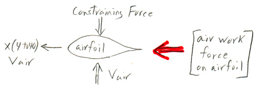
Symmetrical airfoil moving fast perpendicular to wind extracts energy from the wind
due to a force (red arrow) from the air flowing around it pushing in the direction of motion.
This force is usually described as a component of the 'lift' force of the airfoil.
The basic mechanism generating the forward force on the airfoil is a region of lowed dynamic air pressure on its upper (back) front surface. Some of the air the moving airfoil encounters speeds up to flow up and over the back side of the airfoil (losing energy), while air hitting the underside of the airfoil is reflected back making a region of increased pressure. This force is usually described as a (forward leaning) component of the 'lift' force of the airfoil.Wind power equationSpeed ratios
In a wind turbine the tip of the blade is typically moving x7 the (wind) air speed, so angle of attack is [tan^-1 (1/7) = 8.1 degrees]. Glider planes need to extract only a little energy from the 'wind' (decrease in height/sec) to keep flying, so they are able to operate at much lower angles of attack giving them airspeeds of x40 the fall rate [tan^-1 (1/40) = 1.4 degrees].
Pout = [power coefficient] x Pwind
Pwind = [1/2 x air density] x [area swept out by the blades] x [air speed^3]
= [1/2 x rho]
x
[(pi/4 x D^2]
x v^3
where
rho = density of air [1.275 kg/m3] (Wikipedia, 'air density')
D = dia of area swept out by blades (m)
v = velocity of air (m/sec)
Wind energy equation from air energy
As a check of the
equation for Pwind above, which I find in the literature, I made the sketch
below. It shows the kinetic energy (@ wind drift speed) of cylinder of
air that moves through the blade circle in one second. It shows the (1/2)
is included. It also 'exlains' why the power in wind goes as wind velocity
cubed. The reason is that the kinetic energy in air per unit volume goes
as vel^2 and the length of the air cylinder is proportional to vel, hence
the (air) energy flow per second through the blade area goes as vel^3.
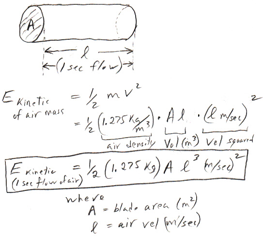
my little sketch of energy in air cylinder
(idealized flow --- ignores fringing)
Let's put in some numbers to check the air mass
Assume 2.0 Mw Enercon E82 with blade diameter of 82 m (270 ft). It performance
curves show this turbine although nominally a 2.0 Mw turbine typically
outputs 2.1 Mw (@ 12 m/sec). At 10 m/sec its output power is 1.6 Mw and
at this wind speed the curves shows its power factor is just a hair under
50% (about 49.5%). The Enercon curve (below) shows the power coefficient
peaks (51%) somewhat a little above mid band near the inflection point
in the curve.
Mass of air (1 sec) = rho x A x length
= 1.275 kg/m^3 x (3.14/4) x (82 m)^2 x 10 m
= 62,300 kg
Wow, 62,300 kg (148,000 lb or 74 tons) of air will pass through the blade circle per second
Air energy check for 1.6 Mw from 2 Mw Enercon turbine
at v = 10 m/s
P wind = 1/2 rho x (Area) x v^3
= 1/2 x 1.275 kg/m^3 x [5,278 m^2] x (10 m/s)^3
= 3.365 Mw
1.6 Mw /3.365 Mw = 47.5%
vs 49.5% (curve)
checks
--------------------------------
Efficiency vs tip speed ratio
The figures
below (from two papers) show how power output from a large variable speed,
variable pitch wind turbine varies (at least in principle) as the blade
speed is varied (relative to the wind) and the blade is rotated (degrees
from flat to the wind). There's a clear maximum at a tip speed ratio of
about 7 (6 to 8) and 0 degrees pitch, so this the operating point nearly
all large wind turbines hold at mid-band wind speeds.
A power coefficient of 0.45 agrees very nicely with the curve below from the above paper (link below), which shows a maximum of about 0.46. Enercon plots the power coefficient with their power vs speed curve and it shows a midpower peak of 0.50.
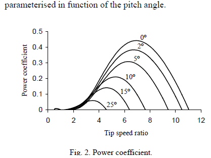
Tip speed ratio is the ratio of blade tip speed to
wind speed
from unpublished Portuguese paper
http://www.aedie.org/9CHLIE-paper-send/296-MELICIO.pdf
Curve below (in red) from a slightly smaller turbine (850 kw, three bladed, 52 m dia, probably a different manuf) is remarkably similar. Same 46% peak efficiency for tip speed ratio of 6 to 8.
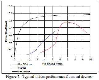
http://www.caspus.eclipse.co.uk/ah/publications/3dmwtucfd.pdf
(blue is an experimental two bladed turbine)
(black is modified Betz Limit)
These papers made no mention of why power should peak near a tip speed ratio of 7, but later when I came to understand the basics of the rather peculiar aerodynamics of wind turbine blades, the tradeoffs (at least qualitatively) began to make some sense. The short explanation from aerodynamics of the blade/airfoil is that power output initially grows as blades rotate faster due to growing forward pointing component of lift force (torque force), but somewhere around a tip speed ratio of 7 where the outer blade is moving at 154 mph improvements in lift begin to be overwhelmed by higher drag, so the curve rolls off. I discuss this matter in more detail (section on blades) later in the essay.
Checking tip speed ratio
It looks like there's an inflection point in the Clipper power curve at
about 2.2 Mw so I'll guess the blade speed hits its maximum [15.5 rpm]
at this power. (For higher wind speeds power would still rise, but
efficiency would begin to fall off.) Since blade speed is proportional
to wind speed at mid power, at 2 Mw (10 m/s wind) the blade speed would
be about [0.9 x 15.5 rpm] = 14 rpm with a period of 60 s/14 rpm = 4.3 sec.
Figuring the circumference from the swept area (blade length doesn't work
because it does not include hub). The ratio of [circumference/sqrt{area}]
is
[circumference/sqrt{area}] = 2 pi R/sqrt{pi R^2} = 2 sqrt{pi} = 3.54
circumference = 3.54 sqrt{area}
tip velocity = circumference/period
= 3.54 sqrt{7,854 m^2}/4.30 sec
= 314 m/4.3 sec
= 73 m/s (@ 10 m/s wind speed)
tip speed ratio = tip velocity/wind velocity
= 73 m/s/10 m/s
= 7.3
check
Tip speed ratio
Tip speed ratio
[tip velocity/wind velocity] = 7.3 agrees very nicely with the curve above.
Keeping the tip velocity 6 to 8 times the wind speed (for this type of
turbine) maximizes the efficiency of the power transfer from wind to blades
(about 45%). Enercon blade patent 6,899,523 (here)
confirms that the blade speed is varied linearly with wind speed.
Since mid-band speed is about 10 m/s for large wind turbines, a tip speed ratio implies the tip speed is about 73 m/sec (in almost all large turbines). In fact Spanish Acciona wind turbines spec the tip speed in their two large turbines: 74.7 m/s at 13.2 rpm (3 Mw) and 73.9 m/s at 18.3 rpm (1.5 Mw).
Another confirmation of tip speed ratio is below. Where possible I have calculated the tip speed ratio (@ 10 m/sec) from the wind turbine specs. In all cases I get between 6 and 7.3 (This is just an estimate as the rotation period at 10 m/sec must be guessed at, extrapolating from the turbine rpm range and the turbine power rating.)
What's the deal with tip speed ratio?
What's
I first saw that wind turbines were characterized in terms of 'tip speed
ratio', and its value always seemed to be near 7, it seemed kind of mysterious.
Rotational air speed varies along the blade, so it was not all clear to
me why tip speed ratio should be a key parameter, nor why it should be
set at 7.
The overview picture is probably something like this. The aerodynamics of blade/airfoils shows the power output initially grows as blades rotate faster due to growing forward pointing component of lift force (torque force), but somewhere around a tip speed ratio of 7, where the outer blade is moving at 154 mph (70 m/sec for 10 m/sec wind) improvements in lift begin to be overwhelmed by higher drag, so the curve rolls off.
The lift equation for airfoils shows the magnitude of the lift force increases as the square of the (relative) speed between the airstream and the airfoil, but a turbine vector wind diagram shows that as the blades rotate faster the airstream hits the blade at a flatter angles, so the lift force vector, which is perpendicular to the airstream, has less forward lean. The result is that the fraction of the lift force that produces torque keeps getting smaller (as blade speed increases), while at the same time as the magnitude of the lift force is getting bigger. Since lift force is increasing as the square of speed, it dominates and the forward (torque producing) component of lift increases with speed. But drag must be increasing with airspeed too, and the peak of the power coefficient curve is probably the tip speed ratio where increases in drag begin to exceed increases in forward lift force.
There's also the issue of angle of attack. At a tip speed ratio of 7 (airspeed of 70 m/sec for wind of 10 m/sec) a vector wind diagram shows the incoming air approaching the blade at an angle of tan^-1(1/7) = 8.1 degree. This means the lift vector is tipped forward by 8.1 degrees, so about 1/7th of the lift force [sin (8.1) x lift force] is pointing in the direction of blade motion and creating power. This puts the angle of attack for the flat oriented outer blade right in the middle of the 0 to 15 degree (useful) range, and it gives it room to rise in the lower and mid regions of the blade, where wind speeds are lower, and yet remain in the useful range so the these blade regions operate efficiently. Hence at a tip speed ratio of 7 the working part of the blade (outer 3/4th) ends up operating with good angles of attack between 8 to 15 (when blade twist is taken into account down near the hub), so each part of the blade generates good lift for the air speed it sees.
Are gliders the key?
The key may be to
look at how gliders are designed. High performance gliders typically fly
100 to 150 mph. The outer parts of wind turbine blades look like glider
blades and work like glider blades. With a tip speed ratio of 7 airspeed
near the tip is 70 m/sec or 154 mph, near the maximum for gliders. A tip
speed ratio of 14 would mean airspeed over 300 mph. If this speed is too
high for gliders, for the same reason (probably drag) it's probably too
high for wind turbines. Too much drag, which in a glider translates to
poor range, in a wind turbine translates to low efficiency.
Energy transfer puzzle
If you consider
the energy transfer between air and airfoil (wing or blade), there is a
big difference between wind turbines and airplanes. The difference is this:
the direction of the energy transfer between air and airfoil is
different in a wind turbine than in an airplane. At first (and 2nd) glance
this is very puzzling because wind turbine blades are essentially rotating
wings and are described by the same lift equation as in airplanes.
An airplane clearly (?) transfers energy from the airfoil (wing) to the air. A plane flying through still air leaves behind a contrail of moving and swirling air, air that clearly has gained kinetic energy. We can see in wing air flow diagrams that air flowing over the top surface of a wing is clearly accelerated in the opposite direction of the planes travel. It seem obvious that the source of the energy imparted to the air comes from the planes engines. In the case of a glider, which I presume leaves a weak contrail, it too has an available source of energy from its loss of potential energy as it descends closer to the center of the earth.
However, NASA emphasizes in its airfoil simulations that an airplane stays aloft because the wind deflects the air downward. Is it possible that the kinetic energy of the contrail air comes from its loss of potential energy not from the plane's engines?In a wind turbine the air-airfoil energy transfer goes the other way, energy (lots of it) transfers from the air to the airfoil. The whole point of a wind turbine is for its rotating blades to extract large amounts of energy from the moving air.
At this point I don't have a good explanation for this difference. I presume that like many problems in mechanics the approach is work out the motions due to forces and inertias, and only then can the energy transfer be calculated. The energy transfers don't dominate, they only need be consistent [energy in = energy out]. It's not hard to think of physics textbook problems where energy transfers seems surprising. One that comes to mind is the row of balls hanging on strings lined up in a row and touching. When a swinging ball hits one end, it stops dead and the ball at the other end flys off. A total transfer of energy from the 1st ball, through many stationary balls, to the nth ball. It's so intuitively surprising that you find this little toy on lots of people's desks.
High wind speed operation
Notice from
the power out vs wind speed curve below (for Clipper) the wind turbine
power maxes out at 2.5 Mw about 12.5 m/s wind speed, but remains operational
(with 2.5 Mw out) as wind speed doubles to 25 m/s. A doubling of wind speed
increase the Pwind x8. There's no way they can allow the blades to pick
up x8 more power because it can't be processed to the line so it would
have to be dumped as heat. Hence the blade pitch and speed need to be adjusted
for a 1/8th lower power coefficient.
The power coefficient curve above indicates how this is probably done. As wind speed doubles from 12.5 m/s to 25 m/s the blade rotation speed is probably kept constant, which lowers [tip speed/wind speed] by a factor of two to about 3 to 4, and the blade pitch is increased to 25 degrees, meaning the blades are rotated so they don't intercept as much air. The curve the shows the power coefficient drops the required factor of 8 to about 0.425/8 = 0.05.
Blade design for high speed survival?
My speculation
(as I write I have seen nothing on this):
I suspect the blades and generator are hard connected together (thru gearbox) and survival of high winds (> 25 m/s) depends on blade design. In pictures of the blades show a substantial twist. It might be that if the blade pitch is high enough the net rotation torque goes to zero. Essentially there would be equal forces from the air on both sides of the blade. This should be clean. Upon switching into the shutdown mode the pitch is increased and the blades probably coast toward zero even with the electronic loading removed, and the mass of the blades would handle transient wind direction changes. [This is right. One manuf says the brakes are applied too, probably only when the speed gets near zero.]
Theoretical
wind turbine efficiency analysis is sketchy
(Update --
The section that follow is my original write up on the Betz Limit, before
I really understood what it implied about the air flow. Following find
'Betz Limit decoded' and 'Understanding the Betz Limit' that reflect my
new views of the Betz model. I now suspect for a simple model the Betz
model is probably pretty good, that it provides a pretty good picture of
of how wind turbines work and reasonable ballpark numbers for air speeds
and wind turbine efficiency.
-----------------------
I read the
Betz Limit, described as the maximum fraction of power which can be extracted
from a moving fluid by a turbine, was 59.3%. This seemed simple and looked
consistent with the 46% efficiency that large turbines were actually achieving,
but upon further reading it's not at all this simple. In fact as of 2009
it appears that no one in the public domain seems to have a clue as to
how to calculate accurately the efficiency of a wind turbine! (In
part because this is because public domain data on blade lift coefficients
and power cofficient vs tip speed ratio is sketchy.)
The Betz model was formulated in precomputer days (1915) and is a very simple one dimensional model, so flow direction changes are ignored. It does not use blades, it uses a thin permeable disk covering the entire area swept out that allows flow through it and extracts some energy from the flow as it passes through. The pressure across the whole disk is assumed uniform. It also looks like there are walls constraining the flow, so the air does does not have the option of going around the high pressure disk area. Does this really apply to a blade system in free flow? Seems pretty unrealistic to me.
In 2001 a Russian and Northeastern guy (Gorban and Gorlov) allow for free flow and account for two missing terms in the Betz model, and they calculate a maximum efficiency of only 30%, only about half the Betz Limit of 59.3%! This is clearly too low since real turbines measure much higher than this (about 46%)! A 2008 paper reviews the all the literature and the best they can do is give experimental results from a medium size turbine that also shows a peak efficiency of 46%.
http://en.wikipedia.org/wiki/Betz_limit
http://www.caspus.eclipse.co.uk/ah/publications/3dmwtucfd.pdf
Wind energy is the total kinetic energy of all its air molecules each with (1/2 m v^2). Power varies as the cube of speed, because double speed increases by x4 the kinetic energy of each air molecules and twice as many air molecules per second flow by. If in a wind turbine you try and all pull all the kinetic energy from air molecules, they obviously no longer flow (v = 0) so (in some sense) they pile up and block the flow. Your continuous power out will fall to zero. If a wind turbine is extracting 46% of the (wind) kinetic energy of the air molecules, it must mean 10 m/s wind going in becomes 7.3 m/s wind coming out (& its area expands 37%), because [1 - 0.73^2 = 0.46].
Betz Limit
The basic power in wind (simplified) is below, where [v = velocity of wind]:Pwind = k x v^3
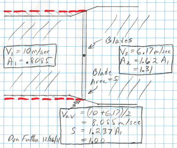
Wikipedia ('Betz Law') shows the Betz model yields the equation below for extractable power from a moving fluid, where (see Wikipedia figure below) v1 is air velocity in and v2 is air velocity out and v = [(v1 + v2)/2] the average air flow at the turbine.
Pout = k x v (v1^2 - v2^2)
Pout = k x (1/2)(v1 +v2) (v1^2 - v2^2)
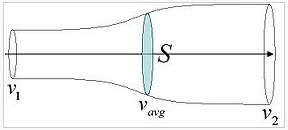
source --- Wikipedia 'Betz Law'Subtle trap?Above equation has a simple interpretation. It is the difference in kinetic energy of air molecules entering and leaving [(v1^2 - v2^2)] x average flow through the turbine [(1/2)(v1 +v2)]. Thus the ratio of wind power than can be extracted is:
Obviously the air mass flowing in and out had to be the same, but the out flowing air (having lost lost kinetic energy) is moving more slowly, so for the same mass (per second) to pass the area of the flow cylinder has to expand as the air slows. The product [vel x area] is a constant, so area expanding inversely to the velocity. At the betz peak efficiency ouput speed V2 is only 33.3% of V1, so the ouput area A2 has expanded to x3 input area A1.I agree with the Wikipedia derivation of the above equation, but there's a subtle point here, a possible trap. As the figure clearly shows the area of the turbine blades (S in figure) is not the same as the area of the input cylinder area. The cylinder is shown expanding as the air slows and the turbine is positioned (sort of) midway at the point where v (average) = (v1 + v2)/2.
If a wind turbine is extracting 50% of the kinetic energy of the incoming wind, then the out flowing air must be moving about 29% slower (v2 = .707 x v1), which means the area of the output cylinder must be x1.41 larger (radius increase of 18.9%).
Pout/Pwind = k x (1/2)(v1 +v2) (v1^2 - v2^2)/k x v1^3
= (1/2) (v1 +v2) (v1^2 - v2^2))/ v1^3
= (1/2) [ 1 + (v2/v1) - (v2/v1)^2 - (v2/v1)^3] Betz equationPlotting the equation above we get the Betz curve:
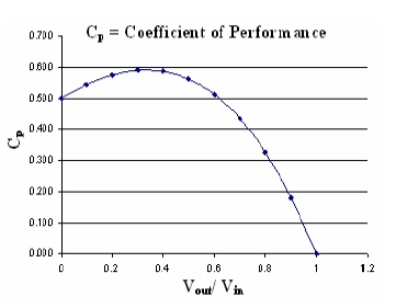
A hint that this model is a little strange is the value at the origin of 50%. On the one hand with [v2 = 0] it appears that all the wind's kinetic energy has been captured, so the recovered fraction of power should be 100%. On the other hand with an output wind velocity of zero, isn't the air just going to 'pile up' and there will be no flow? (Well, the math answer is that the output area has expanded to infinity!) The Betz model generates 50% because the energy term gives 100%, but the average flow (average of 1 and 0) is 1/2. No velocity for the output wind is a weird condition, and the 50% value here is a strong hint the model is not valid at low output wind speeds.What does the betz limit mean?The peak at [v2/v1 = .333] kept bothering me. This means the output wind has only 11% of its kinetic energy remaining! So why isn't the efficiency 89%? The answer is the Pout/Pwind has the pesky term [(1/2) (v1 + v2)], which derives from the turbine area not being the input area but the area of the cylinder where the velocity is average. The value of this term is [1/2 x (1 + .333)] = .666, and (.666 x .889) = 59.3%. Another indication that the betz limit is rather strange.
It took me
a while to figure this out, to really understand the betz model and to
what extend it applies to wind turbines. When I read the long discussion
page of the Wikipedia 'Betz Limit', I found a lot of other people were
bothered too, and I found various takes on the limit. I think I now understand
what the betz limit means.
-----------------------
Betz limit decoded
(1/2/12
update)
The Wikipedia
'Betz Limit' I found had a pretty clean, simple derivation of the Betz
Limit (I later improved it), but no explanation as to the puzzling Betz
results. After thinking about this for a few days, I finally figured out
what was going on --- upstream air as it approaches the blades and expands
forces a ring of air, included in the reference cyclinder, radially outward
such that it bypasses the blades and contributes no power to the
turbine. Nowhere had I ever seen this explained, so I wrote it up and added
it to Wikipedia article 'Betz Limit'.
Key idea
The Betz model
in its efficiency calculation uses for a reference (reasonably) a cylinder
with the area of the blades, but the model shows area of the flow downstream
is smaller than the blade area. According to the model the flow
as it approaches the blades and begins to lose energy expands to exactly
the
area of the blades as it passes through the blades. My insight was
that the expanding air flow shown in the Betz 'milk bottle' flow diagram
must be pushing radially outward a ring of air that surround it! And because
the flow expands to exactly the area of the blades upon passing through
the blades, some of the air in the input cylinder that would be expected
for straight axial flow to hit near the tips of the blades must be bypassing
the blades.
Some of the upstream air bypassing the blades explains why the Betz results (at all speed ratios) show a lower efficiency than would be predicted from the speed ratio! Conversely, it means the downstream air always has slowed more than a simple calculation using Cp (wind turbine efficiency) would predict. I had been assuming that because modern turbines are about 50% efficient (using a cylinder of blade area for power reference), that it was intrinsically obvious that the speed of the downstream air must be .707 of upstream air. Nope, the Betz equations and picture say no, the air exiting the turbine blades slows more than this. For example, at the Betz Limit of 59.3% a simple velocity interpretation would say the air had been slowed to .638 of incoming speed, but the Betz equations say the speed ratio for 59.3% efficiency is only .333, which means air that actually passes through the blades (as opposed to bypassing the blades) has lost 88.9% of its kinetic energy.
From this point of view the 50% mystery is worse! When only air that actually passes through the blades is considered, wind turbine blades are even more efficient than 50%! Below I do a calculation for modern 50% efficient turbines that shows at least 61.9% of the kinetic energy of the passing through air is extracted by the blades.
Understanding the Betz results (12/29/11 addition to Wikipedia 'Betz Limit' by me)
The Betz results are at first glance a little hard to understand. For example, why is the maximum Betz efficiency 59.3%, when a speed ratio of [V2/V1 = .333] implies the air passing through the rotor has lost 88.9 % of its kinetic energy? The left side of the betz curve shows a maximum efficiency of 50% when the exiting air (V2) has no axial velocity. Is this realistic?
The answer to the second question is easy. 50% efficiency at [V2 = 0] is not realistic, the model breaks down at very low exit speeds. The Betz model assumes a constant density fluid and that implies the cross sectional area of the flow varies inversely with axial speed. At [V2 = 0] the cross sectional area is infinite! Mathematically the exiting air does not 'pile up' because it is spreading radially, but radial kinetic energies are not accounted for in the Betz model.
To show that 59.3% Betz efficiency is indeed consistent with a loss of 88.9% of kinetic energy in the air passing through the rotor a physical picture is helpful. The equations for power extracted from the air flow apply to the 'milk bottle' shaped flow shown in the figure at the beginning of this article. The upstream flow (V1) has a cross sectional area less than the rotor area (S). As the flow approaches the rotor, it begins to lose energy, and as it passes through the rotor the equations show it expands to exactly the rotor area (S).
The last step in calculating the Betz efficiency (Cp) is to divide the calculated power extracted from the flow by a reference power value. The Betz analysis uses for its power reference, reasonably, the power of air upstream moving at V1 contained in a cylinder with the cross sectional area of the rotor (S).
The key to understanding why the Betz limit is lower than implied by the speed ratio is to understand that some of the air in the Betz reference cylinder does not pass through the rotor. The area of the flow that will pass through the rotor is upstream smaller than the rotor area. It expands to the rotor area as it reaches the rotor, implying that roughly half the energy transfer from the air to the rotor occurs before passage through the rotor. Thus it must be the case that the air just outside the flow gets pushed radially outward as the rotor is approached just enough so that it bypasses the rotor. The Betz equations do not include any terms for air that bypasses the rotor, its contribution to the extracted power is assumed to be zero.
As a check, let's calculate conditions at the Betz limit: 59.3% efficiency at [V2/V1 = .333]. The equations show the flow speed at the rotor is the (arithmetic) average of V1 and V2, or [V1 (1 + .333)/2 = .666 V1]. For constant density fluid the product of the speed and area are constant everywhere along the flow, so [V1 x A1 =.666 V1 x S], where A1 is the area of the flow upstream at V1. Thus A1/S = .666, meaning only 2/3 of the air in the upstream reference cylinder will eventually pass through the rotor and contribute to the extracted power. Thus the denominator in the Betz efficiency calculation is (in effect) inflated by 3/2, so the efficiency based on speed changes (88.9%) must be scaled by inverse of 3/2, or 2/3. [88.9% x .666 = 59.3%] gives us the Betz limit. Checks.I also added to the 'Betz Limit' in Wikipedia at about the same time the section below on the efficiency of modern large wind turbines, with a footnote to Enercon whose data sheets I found has plots of Cp for its whole family of turbines. I also added an equation for Pwind that explicitly showed the power in the reference input cylinder of air (which much earlier I had derived), and I added a sentence under the milk bottle figure that area 'varies inversely with speed'.
A couple of day later (1/3/12) I realized the Betz curve tells us more than the maximum theoretical efficiency. If the Betz model is correct in implying that a (calculable) fraction of the reference air bypasses the blades, then it can be used to estimate the downstream wind speed of real turbines, so I added to my Wikipedia edit the paragraph below.Modern large wind turbines achieve peak values for Cp in the range of 0.45 to 0.50, [4] about 75% to 85% of the theoretically possible maximum. In high wind speed where the turbine is operating at its rated power the turbine rotates (pitches) its blades to lower Cp to protect itself from damage. The power in the wind increases by a factor of 8 from 12.5 to 25 m/sec, so Cp must fall accordingly, getting as low as 0.06 for winds of 25 m/sec.footnote [4] -- "Enercon E-family, 330 Kw to 7.5 Mw, Wind Turbine Specification" (pdf), links to below
http://www.enercon.de/p/downloads/EN_Productoverview_0710.pdf
The Betz model can also be used to estimate the downstream air speed of real wind turbines. Kinetic energy of wind depends on speed squared, so if a modern large wind turbine is extracting half the wind's energy, which is possible, then from energy considerations it would seem that the downstream air speed (V2) should be x.707 of the upstream air speed (V1). But this is not what the Betz curve shows. Solving the Betz equation for [Cp = .50] yields [V2/V1 = .617] with 81% of the air in the upstream reference cylinder actually going through the blade circle, and 19% bypassing the blades due to a radial outward push from the inner expanding air flow as it approaches the blades.Editing Wikipedia 'Betz Limit' derivation section (12/28/11)
----------------------------P = Cp x (1/2) x density x S x (v1)^3
Pwind = (1/2) x density x S x (v1)^3
The natural reference for the size of the input cylinder for Pwind (Pin) is to set its area equal to the area of the blades. And while it's not at all clear in the way the betz model normally is presented, it does in fact use a blade area reference cylinder for Pin. I edited Wikipedia to make this point more clear, adding an equation for Pwind (power in the input cylinder).
In the case where the quoted betz efficiency is 59.25% (maximum) the area of the airflow that will actually go through the blades far upstream has only 2/3rd the area of the blades. This air, which slows down to 1/3rd of its initially velocity, does in fact have 88.9% of its energy extracted by the turbine. Efficiency is defined as the ratio (Pout/Pin). So what's going on is that the betz model, by calculating Pin using a cylinder with an area the size of the blades, is including a ring of air that will bypass the blades (flow around the outside) and have zero energy extracted from it. The 3/2 larger energy of Pin reduces the 88.9% efficiency (figured from the velocity change) by 2/3rd to 59.3% the betz limit [0.666 x 88.9% = 59.3%].
In other words the betz model when looked at carefully says at any ratio of speeds some of the air in the blade area reference cylinder will be pushed radially outward (by the expanding, slowing inner air) such that it goes around the blades. If this model is valid (it probably is largely true), it makes the efficiency always lower than the input/output speed ratios would predict, or conversely it makes the input/output speed ratios higher than the turbine efficiency would indicate.
Betz
model applied to modern turbines(Dec 2012)
Previously
I had been assuming that for 50% efficient turbines air passing through
the blades was slowing to 70.7% of the initial velocity, but I now think
the betz model is probably right in showing that some air will go around
the turbine blades, so 70.7% is too high. I solved the Betz equations (above)
for [Cp = .50], and the result is [V2/V1 = .617] with 81% of the air in
the (blade area) reference cylinder passing through the blade circle and
19% bypassing it.
Below is a sketch I made showing the expanding air cylinder for a slowing of the air to 61.7% of initial speed. The betz limit for this speed ratio (see below) is 50%, so this is the Betz upper end for a real modern wind turbine. A 50% efficient wind turbine operating with an exit speed of 61.7% of input speed would be at 100% of its betz limit! I drew the sketch on graph paper to show the size of the inner 81% air column that expands to actually go through the blade circle. Since area goes as radius squared, air that goes through the blade circle is in a cylinder whose radius is about 90% of the blade radius. The outer 10% radius ring of air is pushed outward by the inner expanding air as it loses energy to the blades causing it to bypass the blades.
50% mystery => 62% mystery
Note the air actually
passing through the blades (@ .617) retains only 38% of its initial kinetic
energy. So the 50% efficiency mystery becomes the 62% efficiency mystery!
Upper end estimate of input/output velocity values
for a typical large turbine
with efficiency (power coefficient) of 50%.
Speed change probably mostly occurs within +/- 0.3
radius
What does this mean?
I originally
thought above was merely an upper (Betz) limit for the downstream air speed
at 50% efficiency. But thinking about this, if the Betz model really does
captures the key aspects of air flow (my guess is it does), then what this
is telling us is that this is an estimate of the actual downstream air
speed. (And this is the spin I put on it in my Wikipedia edit.)
Betz calculation for above
Here is the
betz efficiency calculation for the figure above.
Pout/Pwind = (1/2) [ 1 + (v2/v1) - (v2/v1)^2 - (v2/v1)^3]
Betz equation
= (1/2) [ 1 + (.617) - (.617)^2 - (.617)^3]
= (1/2) [ 1 + .617 - .381 - .235]
= 0.50
(50% efficiency, lossless wind turbine)
For the air going through the blades (inner cylinder) the efficiency based on velocity changes is [ 1 - .617^2 = 62%]. This is reduced by the increase in Pin by increasing the input cylinder from .8085 A1 to A1 (area of the blades). 62% x .8085 = 50%. So air slowing to 61.7% of the input speed, would mean real turbines are operating right at the theoretical limit predicted by this model. This is the upper end of the output speed, and it could be lower if real turbines operate below the Betz limit.
The betz model says nothing about over what distance the air velocity changes, but from various hints (tip speed = 7 and computer simulations) I suspect most of the speed change occurs within about 0.3 radius on both sides of the blade, so that's how the figure is drawn. I drew straight lines in the figure, but obviously the real air flow would be a smoothed version.
Stepping back
this makes my input puzzle about how the blade extracted 50% of the input
air worse, because of the air actually passing through the blade circle
(vs flowing around the outside) the energy extraction is 62%!
------------------------------------------
My thoughts on efficiency ---
My first thought
is I am totally amazed that large (three blade, horizontal) turbines
can capture anywhere near half the kinetic energy of the blowing air molecules.
Look at the pictures. The most striking thing visually is that the blades
on a large turbine are tiny (tangentially)! The blades only occupy
maybe 3% of the area swept out! This is totally different from a high speed
cooling fan where blades occupy 50% or more of the area swept out. On first
glance it seem that with such small blades, with huge open space and slow
rotation speeds that most of the air molecules would just pass through
without hitting the blades. It's common sense that the air molecules have
to hit the blades, or approach within a distance roughly comparable
to the size of the airfoil (based on airfoil pressure curves), to transfer
momentum and energy to them. If nearly half the wind kinetic energy is
being extracted by the blades, then it seems to me that nearly all of the
air molecules passing through the swept area must be coming fairly close
to a blade.
Airfoil treatment of blade efficiency
The discussions
I find of blade efficiency are usually in terms of airfoils, discussions
of lift, drag and stall. Clearly there is more than a century of experience,
theory and modelling of propellers for airplanes and boats, about which
I know essentially nothing. Visually the blades of a turbine look a lot
like modern helicopter blades, and they may very well be doing basically
(in hovering) the same job. In a hovering helicopter it's got to be a major
objective is to transfer power (or momentum) to the air efficiently to
minimize the power out of the engine.
When operating at the peak of the power factor curve the air is said to provide 'lift' to the blade, and it is the lift that gives (rotation) force and torque. Enercon blade patent 6,899,523 calls the fall off in power factor on the left side of the peak the 'stall' region, defined as higher wind speed (for a given blade speed) causing the air flow to 'break away' (I presume this means laminar flow is lost) from the blade's suction side. The stall causes lift and hence torque to fall off dramatically. (It also points out that stall caused by wind gusts causes a positive feedback. High winds lower torque, which lowers blade rotation speed, which further lowers the tip speed ratio. A classic workaround to prevent blade stall from gusts is to operate a little above the peak of the curve (blade speed a little too high. Gust stall always begins near the hub where blade velocity is lowest. The improvement of the patent is to shape the blade such that only a small region stalls. This has the effect of broadening the power coefficient curve.
2.5 Mw Clipper (USA)
The unusal
feature of the Clipper is that it uses an usual gearbox with four output
shafts. This allows them to use four 1/4th size generators. They use four
PM generators not induction generators. The nacelle (top structure) in
pictures is also very small. One reason it's small is the PM generators
are quite small and all mounted on the same backplate. They say a standard
gear box is a three stage planetary. Instead they use a two stage helical
distributed design that has four output shafts driving four PM generators.
They say the conventional system used brushes and slip rings to excite
the rotor (this is what double fed means). The go to DC and chop it to
AC using high capacity IGBT's. The Clipper has been installed by First
Wind in a big Utah wind farm.
Clipper is manufactured in Cedar Rapids Iowa (their only factory) with factory capacity of 350 turbines per year. From its annual report Clipper appears to be a new US company (offices in UK too) and the 2.5 Mw turbine is their first product. 2008 revenue: 737 million (sold 248 turbines), 2007 revenue: 24 million. Clippers finances in 2009 were strengthened when a big industrial company (company that owns Pratty and Whitney) boought a 50% stake. According to Wikipedia the taxpayers (via DOE and NREL) funded the development of the 2.5 Mw turbine. Clipper spent 300 million on ("remediation"), translation: fixing bad blades in the field !! They hope in future to install 2000 2.5 Mw Clippers in a 5 Gw project called Titan Wind Project located in South Dakota. This project needs government money to build transmission lines to the field.
Liberty Clipper 2.5 Mw (four PM generators)
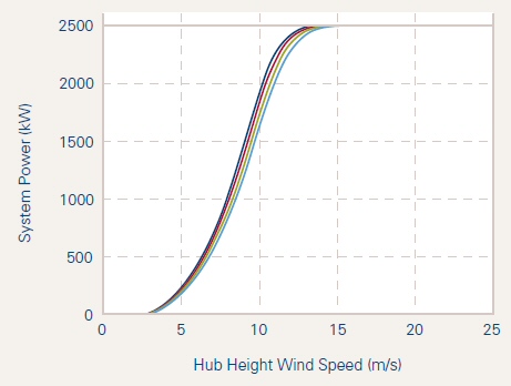
Difference in curves is 13% difference in blade length
(Ref: 10 m/s is 22.4 mph wind)
This curve is interesting. Linearizing the upper part of the S curve it hits saturation at about 12 m/sec. At half this this (6 m/sec) the cubic power relation would predict about 300 kw and that's about what the curve shows. Also there is an inflection point at about 2.2 Mw (10.5 m/s). My guess is that the rotor speed max (15.5 rpm) is at this wind speed and that's why power begins to roll off (maybe with some pitch increase too). The speed spec ratio is 15.5/9.6 = Applying the speced ratio of speeds
Rotor speed
9.6 to 15.5 rpm (6.3 to 3.9 sec rotation time)
Speed ratio
1.61 = [15.5 rpm/9.6 rpm]
Blade length
43.2 m (142 ft)
Tower/hub height
80 m (263 ft)
Gearbox type
two stage helical
Gearbox ratio
73 = [1,133 rpm/15.5 rpm]
Power
2,500 Kw
Voltage
690 VAC
Generator speed
702 to 1,133 rpm
Generator type
synchronous PM (four), 660kw @ 1,133 rpm
DC Link voltage
1,320 VDC @ rated power
817 VDC min (if output rectified)
Power converter
4X, IGBT, six pulse, outputting 690 VAC 50/60 hz
(4x suggests that each PM generator has its own IGBT converter)
(690 VAC would be compatible with 817 VDC bus if it was
peak voltage, and .707 x 690 VAC = 488 VAC)
Tip speed ratio
(@ 10 m/sec)
(3.14 x 2 x 43.2 m radius)/period @ 10 m/sec)/10 m/sec
(271 m/4.45 sec)/10 m/sec
6.1 (est)
The Clipper is quite similar to the Nordex. Clipper speed range is small too at 1.61. The big difference is Clipper uses four small PM generators instead of induction. Also operates at higher voltage, so current in each generator is about much lower, about 500 A = [660 kw/1,329 VDC]. Don't see any survivable wind speed spec on Clipper. German roots? Only factory is in Iowa, but the regulatory qualifications are mostly German.
http://www.clipperwind.com/pdf/liberty_brochure.pdf
Clipper has somehow got its foot in the door to build a really big offshore turbine off UK. In 2008 headline had it at 7.5 Mw, but as of Sept 09 it's now to be a monster 10 Mw turbine. UK government is kicking in millions to build a blade factory in UK for these turbines. Subassembly testing in 2010 and 10 Mw prototype is go up onshore in late 2011. Scale drawings (below) show it dwarfs a 2.5 Mw turbine. From fundamental scaling it needs to be twice as large as a 2.5 Mw turbine to sweep out x4 the area. (It's temping to say 10Mw is approaching the size limit for practical turbines, but people probably thought that about 1.5 Mw units ten years ago!)
http://www.clipperwind.com/pdf/Recharge_18_September_2009_pg_4.pdf
Nordex
2.5 Mw electrical specs (German)
Here is the
usable range power vs speed spec of the 2.5 Mw Nordex wind turbine. This
turbine hits its maximum power about 31 mph, but at 12 mph it is only putting
out 10% of its maximum power.
Rotor speed
10.8 to 18.9 rpm (5.6 to 3.2 sec rotation time)
Speed ratio
1.75 = [18.9 rpm/10.8 rpm]
Blade length
38.8 m (127 ft)
Gearbox type
Planetary
Gearbox ratio
68.7
Power
2,500 Kw
Voltage
660 V
Generator speed
740 to 1,300 rpm
Generator type
asynchronous double-fed (liquid cooled)
Grid connection
via IGBT converter
Tip speed ratio
(@ 10 m/sec)
(3.14 x 2 x 38.8 m radius)/period @ 10 m/sec)/10 m/sec
(243 m/3.8 sec)/10 m/sec
6.4 (est)
Notice the remarkably small working rotation ratio of the blade (& turbine) [18.9 rmp/10.8 rpm = 1.75]. This looks inconsistent with the power range vs speed table. 1.75 cubed is only 5.5, so that would imply a power range for a 2.5 Mw turbine of about 500 kw to 2.5 Mw, but the low end is much lower than 500 kw. Puzzled. In videos of big turbines I count maybe 4.5 sec per rotation, which looks pretty slow, and that fits nicely with the spec range of 3.2 to 5.6 seconds.
The gearbox
steps up the blade speed x68.9 to drive a 2.5 Mw AC generator 740 to 1,300
rpm. Asynchronous means this is an induction generator (induction
motor run backwards). Double fed probably either means its got separate
double windings (or maybe two generators on same shaft). The generator
output AC power is converted to 660 VDC. Very likely AC to DC conversion
is via one or two IGBT controllers that control the induction generator.
|
m/sec |
kw |
ratio (10 m/s baseline) |
|
|
|
|
|
|
|
|
|
|
|
|
|
|
|
|
|
|
|
|
|
|
|
|
|
|
|
|
|
|
|
|
|
|
|
|
|
|
limit |
|
Nordex 2/3/2.5 Mw spec sheet
http://www.nordex-online.com/fileadmin/MEDIA/Produktinfos/EN/Nordex_N80_2500_GB.pdf
Northern Power --- 2.2 Mw direct drive turbine (upgraded
to 2.3 Mw)
Northern Power System
has in development a 2.2 Mw turbine for grid farms. What's very interesting
about the Northern 2.2 Mw is that it's to be a scaled up version of their
100 kw unit, and like the 100 kw unit will have no gear box. It will be
'PM direct drive', so its big PM generator will have to operate at the
blade frequency of a big turbine (10 to 20 rpm), which is three or six
times lower than their current 100 kw turbine (59 rpm). And it will be
operating at a frequency x50 to x100 lower than generators (PM or induction)
in other big turbines.
Northern has raised 50 million to do this development, but is that enough? The other much bigger turbine companies build separate factories just for blades or towers and ship them around the world. Northern is a small company. However, I did see that a sewer pipe company in CA has expanded into making towers, so maybe they can buy some of the components they need. Or maybe if they can develop and prove out their big direct drive PM generator, they can be acquired.Northern Power (update 10/26/11)Hail Mary pass --- Other turbine companies have scaled up the multi-Mw turbines in small steps of two or less: 650 kw, 1.5 Mw, 2.5 Mw. Small Northern is scaling up by x22 (100 kw to 2.2 Mw). Sell stock short? (They built a 1.5 Mw test generator in 2005)
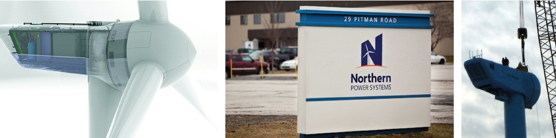
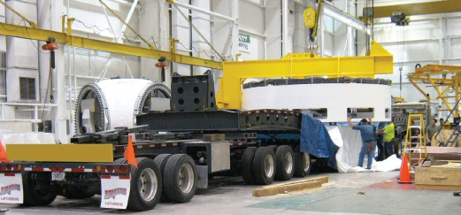
Big news is that as of Mar 2011 Northern Power has brought their 2.3 Mw direct drive turbine to market. Web site says the new owners since 2008 have invested 100 million. They better sell well because looking at the pictures you can see it takes a big factory to manufacture all the huge parts in a 2.3 Mw turbine. As of Mar 2011 they have built and installed a single prototype 2.3 Mw in Michigan (built in a factory they have built in Michigan). A couple of months later they have received orders for two.
Northern
Power 2.3 Mw direct drive turbine
Rated power
2.3 Mw
Rotor speed
10 - 15 rpm (4 - 6 sec rotation time)
Speed ratio
1.50 [15 rpm/10 rpm]
Wind speed
3 m/s (cut in), 25 m/s (cut out)
Hub height
80 / 98 m
Rotor dia
93 m (100 m option)
generator
PM direct drive (no gearbox), liquid cooled
converter
IGBT, proprietary circuit, liquid cooled
grid voltage
10 - 34.5 Kv
rotor (assembly, fiberglass blades)
kg
nacelle
kg
tower (steel)
kg
Tip speed ratio
(@ 10 m/sec)
(3.14 x 93 m radius)/period @ 10 m/sec)/10 m/sec
(292 m/4.6 sec)/10 m/sec
6.3 (est)
Curiously small speed ratio of 1.5. I understand why the speed ratio is small in a double fed induction machine, but not why is it is small in a direct drive turbine. The Enercon speed ratio is over 3: 1.
Conversion converts variable power from PM generator to DC then chops DC to grid freq and up through transformer.
2.3 Mw PM generator ring mounted directly behind blade
hub
PM direct drive generator ring (2.3 Mw)
Really cool animated video from Northern Power showing the inside of the nacelle
http://www.northernpower.com/utility-wind-power/northern-power-2.3.php
Scaling up the generator
Power = [torque
x speed] so to load the blades of the Northern big turbine to extract 2.2
Mw the magnetic torque of the generator will have to be scaled way up from
their 100 kw turbine, maybe x88 = [x22 for 2.2 Mw vs 100 kw and x4 for
15 rpm vs 59 rpm blade speed]. If the air gap in a bigger generator is
the same as in the smaller one (maybe not realistic), then the lateral
(sideways) forces of each small region of the air gap stay constant and
the total local lateral force increases as air gap area (radius x length).
Rotational torque depends on how far from the axis the lateral force is
generated [torque = radius x force], so the torque of the generator will
scale as (radius^2 x length).
In other words the torque of a machine is (approx) proportional to its volume and weight. Low speed for a given power means high torque and high torque means a big generator! First order scaling says the penalty for removing a 100:1 gearbox (for same power) is an increase in weight of the generator by x100! In practice there may be tricks that can be played like making the generator more in the form of a ring with a hollowed out interior (like a bicycle wheel). To scale up a 100 kw generator to 2.2 Mw and account for the lower blade speed, the torque must go up by x88 = [ x22 higher power and x4 lower speed], so the generator needs to expand in each dimension by about a factor of 4.45 = [cube root{88}] and could weigh x88 the weight of the 100 kw PM generator.
Here is a calculation of the torque for the 2.2 Mw unit (I'll use same blade speed for full power as the 100 kw turbine: 13 rpm).
torque = power/w
= 2.2 x 10^6/(13 rpm x (1 min/60 sec) x 2 pi)
= 2.2 x 10^6/(1.36 rad/sec)
= 1.6 x 10^6 n-m x (1ft-lb/1.35 n-m)
= 1.19 x 10^6 ft-lb
One million two hundred thousand ft-lb is a shit-load of torque. I looked up the torque available from a company I used to work with who makes very large PM motors (to 400 hp) for industry (Powertec) and their idea of high torque is 3,000 ft lbs, less than 1% of what this turbine needs. In the ABB large family of turbines for wind they indicate they make (or can make) direct drive PM turbines designed for the low rpm of a large turbine. I can't find any detailed specs, but apparently this ABB direct drive PM generator is good to 1.5 Mw. Does anybody actually use large PM direct drive turbines? Outside of Northern, who has a 2.2 Mw PM gearless in development, I can't find anybody.
Doing some Googling I found large direct drive wind turbines are not new. In an ABB survey paper (2001) of the ten largest wind turbine manuf one of them (Enercon) was already gearless (10 to 24 rpm) at a power level of 1.8 Mw. So what is it that Northern is doing that is new? Maybe its the use of PM in a big ring turbine, or are they just going to buy it from ABB?
Bingo
After writing above [bicycle (form factor) 'trick' to reduce weight & cost] I went to the Enercon site. Their wind turbines are all gearless and go to up to 2.3 Mw. Here is their nacelle. The generator is the large red thing directly behind the blades. It has a huge diameter all the way to the walls of the nacelle, and it does in fact look a lot like a bicycle wheel, you can actually see the spokes!

Northern Power --- 100 kw little brother
A Vermont
company Northern Power System makes a scaled down three blade, variable
speed wind turbine that looks like the big brother of the 2.5 Mw units.
The Northern Power Systems has a blade dia of 21 m, roughly 1/5th of the
(near) 100 m of the big guys, so its swept area is 1/25th and what do you
know its power rating of 100 kw is 1/25th too. It's power curve in terms
of wind speed and shape is very similar to 2.5 Mw Clipper.
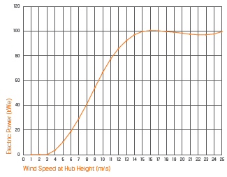
Northern Power Systems model Arctic 21
(gearless 100 kw)
June 2008 news story --- Distributed Energy Systems in CT files for Ch 11 bankruptcy (2007 $49.8 million net loss on revenue of $29.3 million), and Northern Power Systems in VT was their wind division. This is why Northern has been reorganizing and sought new funding. I read their new CEO formerly ran a Codon, a protein company!Direct drive (no gear box)
Rotor speed
xx to 59 rpm (xx to 1 sec rotation time)
Speed ratio
Rotor dia
21 m
rotor (assembly, fiberglass blades)
1,400 kg
nacelle
5,800 kg
tower (steel)
13,800 kg
http://www.northernpower.com/technology/smartview-platform.php
2.3
Mw Enercon gearless (German)
What is interesting
about Enercon is their large wind turbines are different from everyone
elses. Everyone else gear up the blade speed to by x 50 to x100 with a
gearbox so they run their generators at 1,000 to 2,000 rpm. Since [power
= torque x speed], high speed at the generator means low torque, and since
(first order scaling) the weight of an electrical machine goes as the torque,
the gearbox reduces the weight and cost of the generator.
Enercon wind turbines on the other hand have no gearboxs. They couple a low speed , very large dia, very high torque generator directly to the blades. They appear to be the only manuf who builds large turbines this way and have been for over a decade. Northern (in Vermont) has a direct drive PM generator, but the Northern turbine is small small (100 kw), though they do have a 2.2 Mw direct drive in development.
The huge direct drive generators are really the heart of the Enercon turbines, their special technology, so Enercon doesn't buy them from an outside vendor, who, of course, could sell to a competitor. Enercon builds and winds their generators in house. Here's a picture of Enercon factory winding the huge diameter stators. (They emphasize that the winding is done manually, which they say is for quality reasons, but I suspect they have little choice given the size of these beasts.)
Apparently Enercon's gearless design is very sucessful. Wikipedia says this:
Enercon GmbH, based in Aurich, Northern Germany, is the third-largest wind turbine manufacturer in the world and has been the market leader in Germany for several years. As of November 2009, Enercon has installed more than 15,000 wind turbines, with a total power generating capacity exceeding 18.5 GW. Enercon has production facilities in Germany (Aurich, Emden and Magdeburg), Sweden, Brazil, India, Turkey and Portugal.Aloys Wobben, Enercon's chief engineer
Whoops --- After looking at a bunch of Wobben's patents, I find his patent record of 100+ patents is not amazing at all.Quick looks shows Woggen's patents cover every aspect of wind turbines from towers, to blades, to generators. Here is a great resource (in English) to understand wind technology. (It took me two weeks or so researching wind turbines, before I stumbled on the name Aloys Wobben and 'his' wind patents.) Another long time US wind guy I checked for patents is James Dehlsen, formerly Zond now CEO of Clipper, and he has a few, including one on a gearbox with multiple outputs.The first half a dozen patents I looked at were all filed after 2000, all with him as the only inventor, and all have little (to no) real substance and little detail. These are what I call product patents, most of which are not real inventions, and the patent office for that reason should reject them. According to Wikipedia Enercon got in a US patent fight and lost, so it's pretty clear to me that ten years or so Wobben just told his staff and patent people to file for US patents on all significant engineering aspects the turbines (I can see him sending out a memo with a list of topics.) As far as I can see, no real attempt has been made to single out substantial inventions in the filings.
Frankly I also doubt that all this engineering has come from CEO Wobben, that one man could engineeror or 'invent' all the electrical and mechanical aspects of so complex as device as the modern large wind turbine. For example, I'd eat my hat if the electrical designer of the ring generator is also the guy designing the shape of the blades, yet here we have 'inventions' in both areas with only Wobben listed as inventor. (It's illegal to patent someone else's invention even if they work for you.)
http://www.freepatentsonline.com/search.html in 'Inventor' field of Quick Search enter Wobben, Aloys
Notes on Enercon
patents
A few notes
from dipping into Wobben's patents:
* 7,102,248 ** Architecture of 6 Mw Turbine --- For 6 Mw offshore turbine the patent proposes two stators on the generator and then doubling all the downstream components (two 3 Mw level rectifiers, inverters and transformers). But then the patent notes the 3 Mw system is already a doubled 1.5 Mw system (starting from two isolated windings on each stator displaced 30 degrees), so the result is the proposed 6 Mw electronics is four complete copies of 1.5 Mw electronics. This patent clearly shows the generator couples to the DC link using standard 3 phase full wave rectifiers.
Seems to me that doubling up electronics as wind turbines get larger is good engineering. It speeds development and reduces risk. Also power levels in multi-Mw turbines are so high they must be pushing the limits of IGBT inverters. When a x2 size turbine is introduced, there's got to be lots of risk with new blades, generator and tower. Why risk new electronics too, when existing and reliable electronics can just be doubled? Later in production x2 size electronics can always be introduced as a cost cutting measure.* 6,398,502 Reducing Blade Noise from 5-6 m/s Wind --- Here we learn at a narrow wind range of 5 to 6 m/s the blades make an annoying noise that makes wind turbines bad neighbors.
* 7,259,490 Synchronous Machine --- Synchrounous machines have salient poles and are excited by DC currents in exciter poles.
* 7,478,777 Winding Ring Stator with Continuous Wire --- Important to avoid crimp or solder connections in a large rotor with so many poles and slots if it is to be reliable, so patent covers winding with continuous wire. Enercon ring stators of Mw class turbines weight several tons (just the stators!) and for turbines bigger than 4 Mw turbine the stators can be as heavy as 50 ton.
* 7,057,384 Closed loop Hall Current Sensor --- Schlock patent. Just the architecture of a standard current sensor sold commercially by the Swiss for 20 years scaled up to the high currents of a wind turbine.
* 6,256,212 PWM Inverter with Variable Carrier Frequency --- Big whop, hundreds of PWM inverter variations have been known for decades. The PWM inverter (driving the line) varies its PWM frequency through the sinewave cycle: 14 to 18 Khz at low voltages and 500 hz near the peak voltage. This patent shows three phase rectifier configuration coupling the generator to the DC link but instead of it being populated with diodes it's populated with gated diodes (SCR's -- silicon controlled rectifiers).
* 6,522,561 ** Inverter for Driving the Line Using Positive and Negative Half wave Circuits --- Interesting (well maybe, see 'how it works' below). This is an inverter configuration I have not seen before. It's separate half wave circuits for positive and negative current. The patent argument is that this architecture is less prone to a short circuit. (Well maybe, but I suspect the real advantage (if there is one) is that it fails more benignly, meaning a single blown transistor does not short the DC link and blow up the inverter). Sure enough later in the patent it says an advantage of this inverter is less risk of fire in the event of a failure. (Fire is probably a major concern. Videos & pictures of quite a few wind turbine fires are available on YouTube.)
A big advantage the patent says of this configuration (which has more parts) is that each switching circuit 'sees' only half the bus voltage, a real advantage in a super high power inverter. The numbers given in the patent are 660 V for each switching circuit yields a sinewave voltage output of 1,320 volts.What sloppy chop job all these US Wobben patents are is demonstrated by patent 6,522,561. I took another look at this patent to understand how its inverter works. Well I find, as drawn, its page one figure (below), which is always the key figure in a patent, doesn't work. Line outputs U,V are shorted together (magnification shows dots on the lines from S1 and S3) and shorted to ground. Phase W has a line missing.Clearly nobody reviewed the drawings for these patents, certainly not the designer, whoever that might be. I doubt it's Wobben.
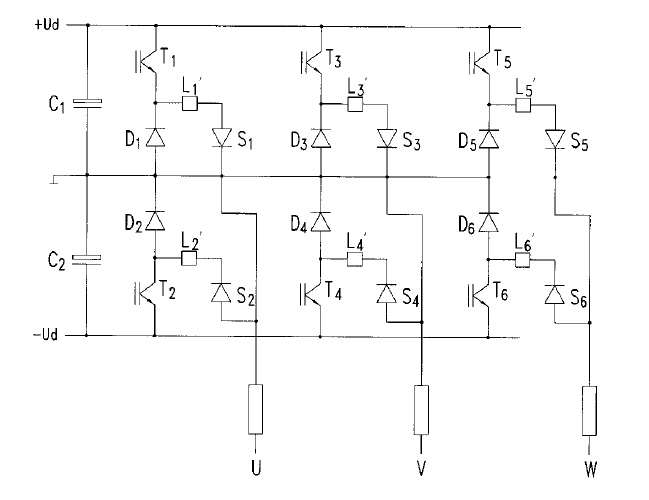
Page one figure from Wobben patent 6,522,561 (filed 9/7/1999)
(If this works, as drawn, I'll eat my hat)
How this inverter works
After getting faked out by S1, S2, identified as 'switches' in the text, (but which I had initially assumed were diodes because they are drawn as diodes!), and the stupid shorting dots and missing W line, I see each phase of this thing is two half wave flyback circuits. Each works for a half cycle of line current (not voltage) as the 'switches' operate with a squarewave cycle of 50/60 hz. Short circuit is 'prevented' because one of switches S1 or S2 is always off. L1' and L2' are described as "decoupling chokes" and "high frequency chokes", implying they are not too large.
Keeping with the schlock patent theme, a key part of this 'invention' is withheld or just sloppily forgotten: the nature & voltage rating of 'switches' S1, S2! So the question is --- What are 'switches' S1, S2?* 6,803,671 Synchronous Machine with Reduced Short Circuit --- Interesting. This patent has scope pictures showing torque, power and blade rotation when the generator has a short.I did a rough sketch of one phase of the patent's inverter showing voltage and current. For a 2.5 Mw turbine with a 1,320 VDC bus (voltage given in patent) the peak current can be easily figured by considering the instant in time phase when one line voltage is at peak (near +bus), and since [sin 30 = 0.5] the other line voltages will be at half peak (approx - bus/2). At this angle the current (Ipeak) flows into one highest voltage phase and returns from the other two phases, which are both at half voltage, hence [Line power = Ipeak x 0.75 bus (approx)].
I peak = 2,500 kw/(0.75 x 1,320 VDC)
= 2,500 A (peak)
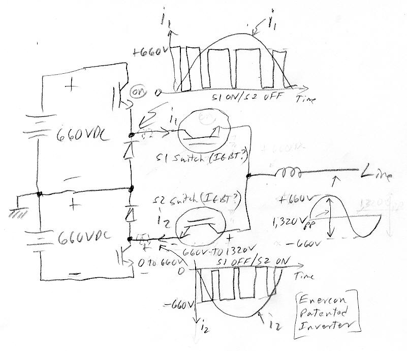
my sketch of the inverter in Enercon patent 6,522,561
For a 2.5 Mw wind turbine with 1,320 VDC bus Ipeak = 2,500 A
(technically 'i2 arrow' shold be drawn reversed, but I thought this would be confusing)My first guess was OFF T2 and OFF S2 would divide the voltage equally, so maybe S2 could be a single IGBT? But I see nothing in the inverter to force equal voltage sharing, which means S would need x2 voltage rating of the IGBT's. (This can be seen in the lower switch of my sketch above.) But it's worse than this since S's are hung between inductors! This can make the voltage unpredictable and peaky. (Whether bidirectional blocking is needed or not I didn't think through.) To make an x2 voltage bi-directional blocking switch from IGBT's take four IGBT's and two diodes per switch, very complicated, expensive and with high loss.
I suppose the 'switches' might possibly be SCR's (gated diode), but this is not the way they are drawn. The switches need high voltage and only need to switch at 50/60 hz rate, which fit SCR's, but SCR's need to latch to work right, so SCR's can only be used only when the polarity of current is predictable. Maybe this is the case with a turbine at high power, but at lower power when filter harmonics are considered the current may not be so predictable.
So now with this insight about the difficulty of building the 'switches' (S) and their curious lack of definition of them in the patent, I suspect this inverter may not used in the Enercon turbines, that this patent is merely covering an exotic possibility someone scribbled out.
* 6,452,819 Inverter and Filter with Reduced Harmonics ---
Wobben teaches an inverter which uses asymmetrical harmonics generated at the output of the inverter stage to reduce harmonic distortion. At the inverter output, the inverter includes a three-phase output choke having a fourth choke leg. The asymmetrical magnetic fluxes produced in the fourth leg by the asymmetrical harmonics are collected by way of three resonant circuits, and then fed back to the negative bar of the DC voltage intermediate circuit which powers the inverter stage. The patentee discloses that the magnetic fluxes in the fourth choke leg flow back into the three main legs of the output choke, thereby increasing the output inductance of the choke. However, the specialized output choke increases the cost of the inverter.* 7,074,011 6 Mw Turbine with Separate Inner & Outer Blades --- Proposal is to add a 2nd small blade to a very large turbine to simplify the main blade design. Patent has some interersting material on air flow. It says the Danes in past used blades with no active inner area. The idea being the 5% or so lost swept area could be made up by making blades 2.5% longer. But what happened was an "aerodynamic hole" was created in the center and the inner active region of the blades did not work right because they did not see laminar flow. (Translation: air was able to divert around the blades going through the center hole.)
* 7,098,551 Turbine with Asychronous Generator --- This patent confirms that Enercon apparently does use slip rings to power the rotor of its synchronous generator! The patent says, "At the present time power is transmitted from the non-rotating part of the turbine to the rotating part of the turbine by means of slip rings." No numbers are given, but I would guess this power is probably in the range of 1% to 3% of the turbine's power.
Something I hadn't though of is all big turbines very likely need power on the (rotating) hub/blade assembly to run motors controlling the pitch of the blades. The slip rings to the hub are thus powering these pitch motors as well as the stator of the direct drive genertor.
E-126
7.5 Mw world's largest wind turbine
Enercon now
has a 7.5 Mw turbine (E-126), world's largest, for offshore (& onshore
too on river banks) use with 13 installed. E-126 has a rotor dia
of 126 m and uses a precast concrete tower (instead of steel). The tower
is 131 meters (425 ft, eq to a 42 story building!) Clearly their direct
drive ring generator has proven scalable. Getting more torque and power
may be a simple case of just scaling up its size as the whole structure
gets larger. More of the same local poles and magnetics (with larger radius
and circumference) would naturally scale up the torque and power.
It's manually wound, so no problem there.
The nacelle dia is not given, but looking at the men in the (left) photo below it's probably in the range of 30 ft. Is it this large to hold the 7.5 Mw generator ring? I at first thought so, but maybe not. For one thing a new 3 Mw Siemens direct drive generator nacelle is only 14 ft (4.2 m) in dia. And in the right photo look at the blade attachment to the hub. It looks like the large hub/nacelle dia is needed just to physically mount the huge blades this thing has. I saw a reference saying the nacelle is heavier in direct drive turbines than in turbines with gearboxes and looking at these pictures of the E-126 nacelle I can believe it!
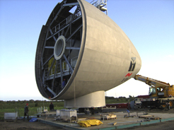 .
.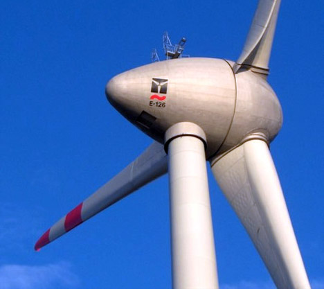
Holy shit --- look at the size of this 7.5 Mw E126
nacelle on the ground (left)
(tiny figures in lower left are men!)
(We probably see the generator at the opening)
There are (virtually) no Enercon turbines in US, but Wikipedia explains the reason: Due to a patent dispute they were forbidden from selling in the US until 2010.
PM or not PM?
Curiously
they never identify the generator as PM.. If it is PM, I would expect them
to say so, since PM generators are a major feature widely touted. Is it
possible it's not PM? Well yes it is!
I found a 2000 (filed) Enercon patent application (below). This patent is worth reading because it appears to have a lot of info about the Enercon turbines, even identifying the Enercon models by number.
http://www.freepatentsonline.com/20030173935.pdf
The above patent has inventor: Aloys Wobben, who seems to be their key guy. His invention were the subject of the law suit Wikipedia talks about. (Enercon claims Kenetech in US stole and patented a key Wobben invention before he did.) The patent says the concepts described could be used to upgrade the rating of the E-66 turbine from 1.5 Mw to 1.8 Mw. The patent is showing how 1/3rd of the flux current of the machine, previously provided only from the rotor, can be provided by current pulses from capacitors on the stator side (because the stator voltage is trapezoidal in shape). So clearly (as of 2000) the Enercon generator is not a PM generator. This does make sense, because this monster is so large, that it would probably be very expensive if the rotor was filled with PM.
Generator output is shown coupled to the DC link through a rectifier not an inverter. Since it is unlikely they weaken the flux at highest speed and power, the large speed variation must translate into a DC link voltage variation of > 3:1 The patent talks of wound rotor being excited, which presumably means it has slip rings(!), but I don't see any direct reference to slip rings.
Slip rings?The stator is wound with two sets of three phase winding displaced 30 degree mechanical each of which handles half the power. It is argued the advantage of this arrangement is L is doubled (not obvious to me why), so short circuit fault currents are halved. Apparently a big advantage of this is protection of the blades, the braking torque seen by the blades is reduced in the event of short in the generator.
Does Enercon generator need slip rings? Seems unlikely in a low maintance design, but how to they power the rotor, which the patent makes clear provides most (or all) of the flux in the machine? They might have a small exciter (or PM) coils on the stator. It would need only to provide the copper losses on the rotor. (This is my best guess.) Unsolved problem --- I have been unable to find out how Enercon powers their rotor.Yes, slip rings
Apparently Enercon does us slip rings to power the rotor! Enercon (Wobben) patent 7,098,551 says, "At the present time power is transmitted from the non-rotating part of the turbine to the rotating part of the turbine by means of slip rings." No numbers are given, but this would be a relatively small amount of power. I would guess it's in the range of 1% to 3% of the turbine's power.
Number of generator poles is 72 or 84. The electrical frequency of the blades is really low [6 to 20 rpm <=> 0.1 to 0.33 hz]. In principle the genertor frequency is unimportant if (!) the waveforms are sinewaves, because in a three phase system with sinewaves power flow to the DC link is constant at all frequencies. However, the patent shows substantial deviations from sinewaves (strong current pulsing), and a higher electrical frequency is useful too (maybe essential) to even out the termperature rise of motor windings and diodes in the rectifier. A multi-pole machine increases the ratio of electrical to mechanical frequency by the number of pole-pairs, so an 84 pole generator raises the frequency x42, so [0.1 to 0.33 hz] mechanical becomes [4.2 to 14 hz electrical].
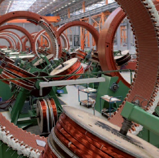
Enercon winding the high torque generator rotor
(winding is done manually)
(hard to judge size, but maybe 10-12 ft in dia?)
Wow, the generator runs hot. A graph shows the internal copper wire at about 145C (very likely at rated power), which for a 40C ambient (104F desert ambient) is a temperature rise of 105C. (Winding surface is about 90C.) For comparison temperature rise for industrial motors is usually in the 30C to 60C? range.
Enercon
2.0 Mw gearless spec
This turbine
(E82) is designed for medum winds. Its curve is below. Enercon also makes
a higher wind speed version of this turbine (E70). The E70 puts out 2.3
Mw even though it blades are substantially shorter (71 m dia), but they
rotate faster and operate over a wider range (6 to 21.5 rpm).
Rotor speed
6 to 19.5 rpm (3.1 to 10 sec rotation time)
Speed ratio
3.25 = [19.5/6]
Rotor dia
82 m
Swept area
5,281 m^2
Gearbox
none (turbine direct coupled to blades)
Cut out wind speed
28 to 34 m/s
Power
2,000 Kw
Voltage
Generator speed
6 to 19.5 rpm
Generator type
Enercon direct drive synchronous annular generator
Grid connection
Tip speed ratio
(@ 10 m/sec)
(6.28 x 41 m radius)/period @ 10 m/sec)/10 m/sec
(258 m/3.54 sec)/10 m/sec
7.3 (est)
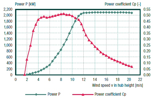
Enercon E82 (2.0 Mw) direct drive wind turbine power
and power coefficient vs wind speed
(Note, high coeffiecient of 50%)
Wow, Enercon gets a great power coefficient factor of 50% (vs 45% for standard large turbines), and it holds it flat from 4 to 11 m/s wind (wind speed range = 2.75). This broad high efficiency range has got to be due to the wide rotation speed range (ratio of 3.25 to 3.5) of Enercon turbines, about double what most other turbine manufs use.This allow them to hold the tip speed ratio fixed (at 7) over a wider speed range.
The high speed version of the E70 turbine has substantially shorter blades (71 m dia), yet has 15% more power out (2.3 Mw) with an rpm range 6 to 21.5 rpm. I first though the efficiency of the E70 (not given) must be much higher than the E82, because its swept area is only 3/4th of the E82 yet it has 15% more power out, but maybe that's not the case. It could just be that the E82 turbine hits rated power at x 1.15 higher speed (about 14 m/sec) than the curve above. At x1.15 higher speed the wind has [1.15^3] = 1.53 more energy, so higher power out (at higher speed) need not require higher efficiency.
Enercon power coefficient calculation @ 8/m/sec
P wind = 1/2 rho x [(blade area] x v^3
= 1/2 x 1.275 kg/m^3 x [5,281 m^2] x (8 m/s)^3
= 1.724 Mw
power coefficient = P electrical/P wind
= .830 Mw/1.724 Mw
= 48% vs 50.5%
(on graph)
check
Enercon power coefficient calculation @ 10/m/sec
P wind = 1/2 rho x [(blade area] x v^3
= 1/2 x 1.275 kg/m^3 x [5,281 m^2] x (10 m/s)^3
= 3.367 Mw
power coefficient = P electrical/P wind
= 1.60 Mw/3.367 Mw
= 47.5% vs 49.5% (on graph)
check
Summary
Turbine manufacturers
(should) know electrical power out vs wind speed quite accurately, because
both electrical power and wind speed can be easily and accurately measured.
My experience as an engineer is that a typical curve on a product
specification, like the power coefficient curve on the Enercon E82 turbine,
is usually quite accurate. The Enercon curve shows its E82, 2 Mw turbine
with a power coefficient that is (basically) 50% at mid-band speeds. A
simple ratio calculation of the electrical power out vs the power contained
in wind in a cylinder with the diameter of the blades (both hard
numbers) gives values of 48% and 47.5% at 8 and 10 m/sec wind, about 2%
lower than the values on the Enercon curve.
I am tempted to say that taken together this shows that real wind turbines can extract just about 50% of the wind energy in a cylinder the size of the blades. However, there is a little caveat. Enercon doesn't define the power coefficient. For example, is their reference a cylinder the size of the blades? Are they specing power to the grid (what the customer cares about) or power captured by the blades? It is a ittle troubling that their numbers are about 2% higher than the electrical power to cylinder power ratio, because electrical power to the grid would be expected to be 1% to 2% lower than the power captured by the blades due to principally to electrical losses in the generator and conversion of the power to the line frequency.
Gearbox issues?
I found link
below with posts discussing gearbox problems in turbines. One poster claims
the Clipper gearbox with four outputs does not (& cannot) share its
loads properly. Another poster has a list of news articles about gearbox
problems at several firms, saying they fail in less than five years. Same
link also says GE has cancelled their 3.6 Mw turbine for Cape Wind, and
are looking to buy (or bought) a firm with direct drive turbines.
Gearbox problems might explain why Enercon with their direct drive (no gearbox) design is doing so well. I wouldn't be suprised if a lot of the direct drive technology is patented by Enercon, since they have been working this concept since the early 90's and they clearly believe in patents.
Direct drive turbines coming from Siemens and GE (4/10
update)
An article
in Technology Review says both Siemens and GE are moving to turbines without
gearboxes. Siemens has a 3 Mw prototype and GE a 4.1 Mw prototype. Siemens
is furthest ahead. They have one up and will install 10 more in 2010 in
Denmark, going into full scale production in 2011. GE's production date
is 2012. GE (as usual) bought their technology, in this case from ScanWest
in Norway.
There are summer 2011 reports that five offshore wind turbines to be installed in Lake Erie in 2012 will be 4.1 Mw GE direct drive turbines. GE marketing dept is working overtime calling them "next generation" wind turbines (never mind that Enercon has been building direct drive wind turbines for years), and they are making the ridiculous claim that they are 25% more efficient. For this to be true efficiency would have to rise from say 40% (one bad turbine) to 50%, or 44% to 55% (good luck).
The Technolgy Review article discussed unreliability of gearboxes, and Siemens makes the (unlikely) claim that their direct drive turbine has half the parts of their earlier turbines. There is no mention in the article of other companies have any trouble with Enercon direct drive patents.
Siemens 3 Mw direct drive wind turbine (SWT-3.0-101)
Rotor dia
101 m
Swept area
8,000 m^2
Gearbox
none (turbine direct coupled to blades)
Hub height
80 m
Power
3 Mw
Generator type
PM (rare earth) mounted on rotor ring (stator core)
Nacelle dia
4.2 m (13.9 ft)
Nacelle length
6.8 m (22 ft)
Nacelle weight
73 metric ton (12 tons less than their 2.3 Mw geared turbine)
Blade material
fiberglass reinforced epoxy resin
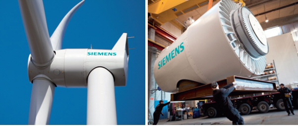
14 ft dia nacelle of Siemens (prototype) 3 Mw direct
drive turbine (model SWT-3.0-101)
GE's direct drive generator is also PM. A US startup, Bolder Wind Power, is trying to develop a 1.5 Mw direct drive wind turbine. Founder is Sandy Butterfield, who was chief engineer for the U.S. National Renewable Energy Laboratory's (NREL).
A new company (CWind of Canada) has an idea to reduce stess that often comes from gusts of wind. Their idea is to replace the gear box with multiple rubber friction tires rolling on the outside of big flywheel that is hard coupled to the blades. The tires are designed to slip during a wind guest. For a 2 Mw turbine eight tires would couple to eight 250 kw generators. They now have a 65 kw test unit and hope to build a 2 Mw prototype in 2011.2.1 Mw from India (Suzlon)
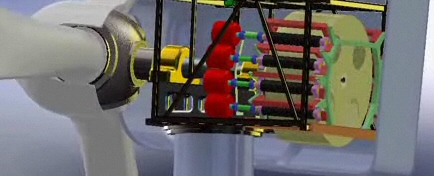
CWind's idea for coupling blades to multiple generators (red) using tires (black) rolling on a flywheel
Rotor speed
15.0 to 17.9 rpm (3.8 to 3.35 sec rotation time)
Speed ratio
1.193 = (1.092)^2 = [17.9 rpm/15.0 rpm]
Rotor dia
88 m
Gearbox type
3 stage (planetary + 2 helical)
Gearbox ratio
118.1
Power
2,100 Kw
Voltage
600 V
Generator speed
1,771 to 2,114 rpm
Generator type
asynchronous double-fed (w/slip rings)
Grid connection
via IGBT converter ?
Has a lot of technical info:
http://www.suzlon.com/pdf/S88%20product%20brochure.pdf
3 Mw Acciona
(Spanish design)
Spanish company,
Acciona, opened a factory in Iowa in 2007 to manufacture for USA, initially
making a 1.5 Mw model with a 3 Mw model (AW-3000) soon. Acciona wind turbines
being moved from the Iowa factory were featured on a TV show about extreme
truckers (BK Trucking). Interestingly the 1.5 Mw turbine is mounted on
steel towers (82 m high with 82 m dia blades), but for the 3 Mw turbine
they switched to concrete towers (120 m high with 116 m dia blades). AW-3000
(3 Mw) specs:
Rotor speed
13.2 rpm (nom) (4.5 sec rotation time)
Speed ratio
1.71 = (1.31)^2 = [19.1 rpm/11.1 rpm]
Tip speed
74.7 m/s (nom)
Rotor dia 109 m (9,311 m^2 swept)Acciona 1.5 Mw model has almost exactly the same tip speed (73.9 m/s) formed by 76.7 m dia rotor assembly rotating at 18.3 rpm.
Power
3,000 Kw
Voltage
12 kw ("medium voltage")
Generator speed
924 to 1,584 rpm (60 hz)
Generator type
asynchronous double-fed ("wound rotor with excitation
by collector rings")
Grid connection
stator of induction generator is directly connected
(via breaker) to 12 Kv line (no transformer)
Inverter & control
based on INGECON-W
Tip speed ratio (est)
(@ 10 m/sec)
(6.28 x 54.5 m radius)/period @ 10 m/sec)/10 m/sec
(258 m/3.54 sec)/10 m/sec
7.3
Electronics (& probably generator) come from GE of Spain (InGeElectric).
http://docs.ingeteam.es/catalogos/Grupo_eng.pdf
Cape Wind
(update 9/4/15)
It's now 6 years since I wrote about Cape Wind in this essay and 14 years
since work on Cape Wind began, and still no construction. According to
an article in the Wall Street Journal today the project is now hung up
by a contract dispute between Cape Wind and the utilities that will be
buying the power. As of 2015 there is still not a single offshore wind
turbine in the USA.
It's beginning
to look like the first offshore wind turbines in the USA will be installed
nearby, off the coast of Block Island in RI.
-------------------------
Cape wind
project, located offshore near Nantucket, MA, has been in the planning
and permitting stages for years. It will be the largest offshore wind farm
in USA. (Actually as of Nov 2009 according to NYT USA has zero offshore
wind turbines) They propose to install 130 3.6 Mv turbines with 454 Mw
rating for the whole farm, mounting them in a rectangular grid with rows
about 1/2 mile apart and about 1/3rd mile spacing between turbines in each
row. For perspective the size of Cape Wind (454 Mw) is 58% the size of
Roscoe Farms in Texas the largest wind farm in the USA. (When first proposed
in 2001, they were going to use 2.5 Mw turbines (170 of them), but in 2004
they upgraded to 3.6 Mw turbines dropping the number of towers from 170
to 130, holding Mw total for the farm the same.) Average output (from
environmental report) is projected to be 170 Mw, which means capacity is
37.4% [= 170 Mw/454 Mw].
Jan 5, 2010 NYT reports another delay for Cape Wind, as wind opponents play the Indian card. NYT says MA Gov and strongly supports Cape Wind and Obana strongly support wind power, yet after ten years still no approval! Look at the map below and see where the Indian land is located. Indians also claim foundations for turbines may destroy tribal artifacts, which are mile offshore in the open ocean! What crap.
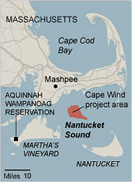
Here is the 130 turbine grid pattern relative to land.
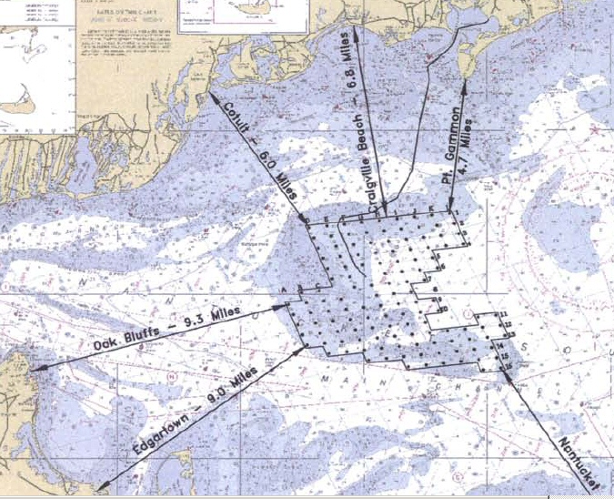
Proposed (2004) 130 3.5 Mw turbines in Nantucket Sound
(24 square miles)
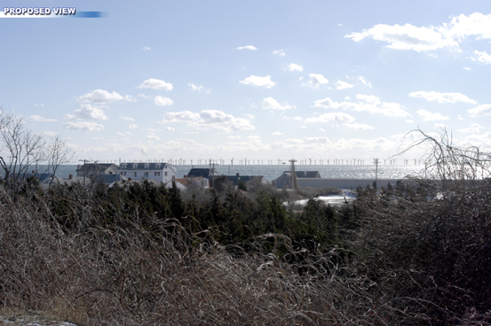
(simulated) view of offshore turbines from Craigville
- 6.5 Mile distance
The average wind speed measured over three years at the site is 8.83 m/s (20 mph).
NYT Editorial 1/8/10Cape Wind carefully avoids saying anything at all about whose wind turbine they plan to use (why?). Even in the huge US Corp of Army impact report it doesn't say, but a cross-section drawing of the nacelle for 3.6 Mw turbine is provided by GE Wind. GE Wind's site lists a 3.6 Mw turbine for offshore use, but there are no specs. This is probably because it won't be built until Cape Wind places an order! (GE does make a 2.5 Mw with full specs.) With more Googling I did find a brochure on the GE 3.6 Mw offshore turbine. GE has had engineering prototypes of the 3.6 Mw operating in the Irish Sea since 2004. (On the other hand 2008 posters note that GE had recently announced cancellation of the 3.6 Mw turbine!)
Cape Wind and its 130 turbines would be located in what may be the most propitious offshore site in the country: shallow water protected from heavy waves; strong, steady winds; and proximity to consumers and industries that would benefit from its power. We hope the administration can persuade the various sides (Translation: buy off the Indians!) to quickly reach a compromise that preserves the core of the project. If not, Mr. Salazar (Energy Secretary) can and should decide on his own to allow Cape Wind to proceed.
As of Dec 2011 Wikipedia shows Cape Wind will be using Siemens 3.6 Mw wind turbines. Siemens wind turbines are built in Denmark (5,200 employees). This company is basically the old Danish wind turbine company Bonus that Siemens (of Germany) bought in 2004. They have installed half the off-shore wind turbines in Europe, so this looks like a good choice from the technology viewpoint.
http://www.gepower.com/prod_serv/products/wind_turbines/en/downloads/ge_36_brochure.pdf
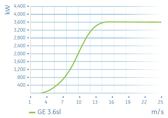
GE 3.6 Mv offshore wind turbine
(yikes, grid not aligned with numbers)
Cut in spec --- 3.5 m/s
Cut out spec --- 27 m/s
Rated speed --- 14 m/s
(update Dec 2010)
Cape Wind
has been approved and construction set to begin in 2011. Projected cost
per kwh of its power in 2013 is 18.7 cents/kwh, about double the current
cost of fossil fuels (says Boston Globe).
(update Nov 2011)
A Nov 2011
court ruling has overturned an FCC ruling that the Cape Wind would not
be a local flying hazard, sending the matter back to the FAA for reevaluation.
Planes landing at some local airports pass are within 500 to the side,
or 1,000 feet above, the turbine site, so there is concern that pilots
landing using visual sight rules would need to be rerouted.
Deepwater
wind --- wind turbines off the coast of Block Island RI (Dec 2010)
(update 7/24/15)
NYT reported
today that a flotilla of ships and cranes are off the coast of Block Island
are visible as the installation of the huge supports for the five wind
turnbines of Deepwater Wind is beginning.
(update 7/4/15)
According
to a recent article in the WSJ it appears that the first offshore wind
turbines in the USA will be installed off the coast of Block Island in
RI. It reports the project is fully permitted and financed and that within
the month construction is going to start on the underwater mounts for the
five turbines. In about a year (Aug 2016) the wind turbines will begin
to be installed.
The five wind turbines will be big, 6 MW units. The turbines will provide power for block island, where about 1,000 people live, with the excess power going to the mainland through a new 100 million underwater cable. A study on the Deepwater site shows the average annual power could be nearly 50% of the turbine's peak power rating as the average wind high up offshore is about 20 mph. These turbines are expected to lower the cost of electricity on Block Island by 30% as its electrical power now comes from expensive diesel generators. (There was no mention in the WSJ article of the much larger 1,000 MW Deepwater project discussed below.)
Alstom 6 MW turbine
(7/4/15)
The WSJ article
says the 6 MW turbines Deepwater will use are Siemens units. However, the
Deepwater site has a Feb 2014 news report that they signed contracts with
Alstom to buy their 6 MW (Haliade 150 model), and Alstom on their site
says the same thing. Alstom? I never heard of them. I did a search of this
essay and no Alstom, so that means in 2009 when I wrote most of this essay
Alstom was not a factor in wind turbines. I couldn't figure out from the
Alstom site where they were based, but Wikipedia says they are a French
company. Effectively Alstom is the GE of France and like GE they get into
new businesses by buying them. The got into the wind business by buying
the (large) spanish wind turbine company Ecotècnia, whose acquisition
they completed in 2012.
The Alstom site says the Deepwater installation of their 6 MW Haliade 150 model will be the first commercial installation of this model, apparently the only other one ever built is the prototype operating off the coast of Belgium. Since it's brand new, it may be that Alstom can't deliver which is why the WSJ is saying Deepwater is going to use a 6 MW Siemens unit. However, a little googling shows that Deepwater had earlier (2011) announced that they were going to use a 6 MW Siemens turbine. From the dates and the fact that the 6 MW Alstom unit is currently mentioned on both web sites, it looks to me like Deepwater has probably switched their turbine supplier from Siemens to Alstom. The fact that WSJ got it wrong is a little surprising, but not too surprising since this is a business newspaper.
The Alstom unit is a PM direct drive turbine. Below is a picture of the Alstom unit. Notice how small the nacelle is. Most large wind turbines have huge nacelles. This must be the result of using a large diameter direct drive PM generator design that eliminates the large gear train. This looks like the way to go in large turbines as it must cut costs. The red thing in the back is apparently a service platform. It looks like it's probably not possible to walk around inside this thing. I bet most of the nacelle is the PM generator whose diameter sets the diameter of the nacelle.
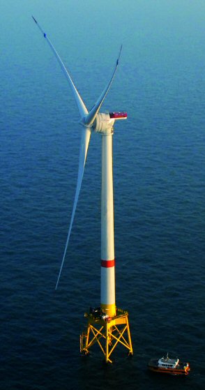 .
. 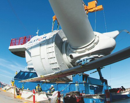
Alstom 6 MW Haliade 150 model offshore wind turbine
(Notice the small nacelle)
Deepwater wind (update Dec 2011)Deepwater wind is also partnering with Garden State Offshore and as of Feb 2011 they are proposing a 1,000 Mw wind farm off the coast of New Jersy.
Deepwater wind still active, as of Oct 2011 they submitted a plan for the 1,000 Mw deepwater site with operation to begin by 2017. In the meantime they are moving forward with a small 30 Mw project (205 million) off Block Island RI. They have signed an agreement with Siemens to buy five of their new 6 Mw turbines for this site. Construction to begin in 2013 or 2014 dependent not only on permitting, but Siemens finishing the design of the 6Mw giant. With Cape Wind again in trouble, Deepwater is claiming they may be the first with offshore wind in USA.
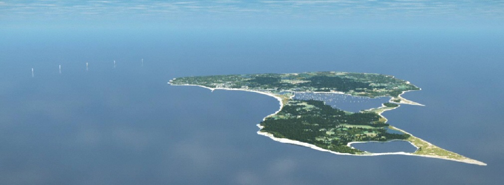
View of five 6 Mw Siemens wind turbines off Block Island, RI (from a Deepwater wind video)
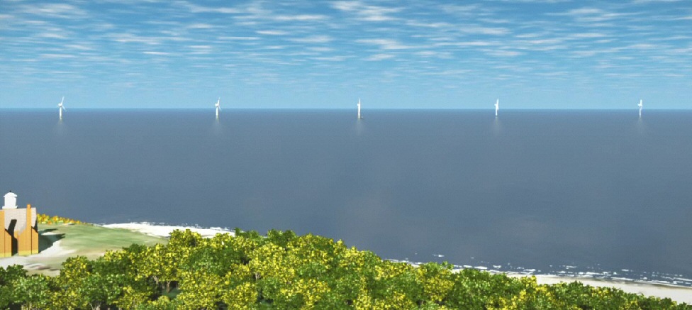
How the five 6 Mw Siemens wind turbines will look from Block Island (from a Deepwater wind video)
Electrical specs on GE Wind 3.6 Mw
GE toots the
advantages of PM generators on their 2.5 Mw model, but in their 3.6 Mw
they are using double fed asynchronous generators. (Maybe larger PM generators
aren't available? ABB makes them)
GE 3.6 Mw
(offshore) wind turbine (cancelled)
(update Nov 2011)
The
link to GE wind turbines shows GE no long has a 3.6 Mw model, but they
do have a replacement. It is 4.1 Mw, 113 m rotor dia, direct drive
wind turbine designed for off shore use. (Specs are skimpy compared
to 2.75 Mw model implying it is in develoopment.)
Rotor speed
8.5 to 15.3 rpm
(5 to 13 rpm Siemens 3.6 Mw)
Speed ratio
1.80 = [15.3 rpm/8.5 rpm] (2.6 Siemens)
Rotor dia
111 m
(107 m Siemens)
Swept area
9,677 m^2
(9,000 m^2 Siemens)
Rotor blades
3
3
Gearbox type
3 step planetary
(3 stage planetary helical Siemens)
Gearbox ratio
(119 Siemens)
Power
3,600 kw
(3,600 kw Siemens)
Voltage
(690 V Siemens)
Generator speed
(1,500 rpm Siemens)
Generator type
double fed asynchronous
(asynchronous Siemens)
Grid connection
pulse width modulated IGBT
Tower
steel (mounted on 85 ft mono-pile in seabed)
Rotor blades
fiberglass reinforced epoxy
Wind 14 m/s to 25 m/s
3.6 Mw (rated max power)
Wind > 25 m/s
bladed pitched to prevent rotation
and brake locked
Lightning protection
copper plates on tips (w/grounding wire)
Tip speed ratio (est)
(@ 10 m/sec)
(3.14 x 111 m radius)/period @ 10 m/sec)/10 m/sec
(349 m/5 sec)/10 m/sec
7.0 (est)
Each turbine connects via a 33 kv submarine cable to a central facility in the center of the array. It couples the power from all towers to the grid via two 115 kv AC submarine cables that come to shore at Falmouth.
Here is a 2008 overview article of the project by the two chief engineers:
GE
Wind 2.5 Mw turbine (USA, formerly Zond/Kenetech)
GE manufactures
wind turbines in Germany, Spain, China, Canada, and USA. GE's installed
base of 1.5 Mw turbines is 12,000 worldwide. Dec 2009 GE signs a contract
for 1.4 billion to provide 338 2.5 Mw turbines to a 30 sq mile wind farm
in Oregon to be built 2010 to 2012. This works out to 4.14 million per
turbine. The Farm operator when installation, roads etc are included figures
total cost of about 2 billion, which is 5.9 million per turbine.
Rotor speed
(wider range than others)
Rotor dia
100 m
Swept area
7,854 m^2
Gearbox type
Gearbox ratio
Power
2,500 Kw
Voltage
Generator speed
Generator type
Brushless PM generator
Grid connection
Kenersys
2.5 Mw turbine model K100 (11/27/12)
Researching
a new local large wind turbine a new company name poppped up, 'Kenersys'.
Three huge (2.5 Mw) Kenersys wind turbines are now going up in Gloucester
MA near the ocean. I had never heard of Kenersys. Looks like an Indian
company bought up GE wind in Germany, and the company has a few dozen turbines
installed. There is an engineering team in Germany and assembly plants
in Germany and India. Here is their blurb:
"Many of the company's 40 engineers in Germany formerly worked for General Electric in Europe. Kenersys has two turbines factories, one in Germany and one in India. About 30 Kenersys turbines are already operating, in Germany, Sweden and India."The 2.5 Mw Gloucester turbines (near the Varian plant) claim to be the largest wind turbines on the east coast. They also have installed a 2.5 Mw wind turbine in Ohio that was made in Germany.
Rotor speed
14.1 rpm @ rated power
Rotor dia
100 m (165 ft each blade from hub center)
Swept area
7,854 m^2
Turbine hub height
279 ft (85 m, taller available, 100m, 135m)
Blade tip height
444 ft (444 ft = 279 ft hub + 165 ft radius)
Tower
tubular conical steel
Gearbox type
Gearbox ratio
117 (117 = 1,650 rpm/14.1 rpm)
Power
2,500 Kw
Voltage
690 VDC (600 V converted to 4,160 VAC)
Generator speed
1,650 rpm
Generator type
synchronous
Grid connection
(active) thristor rectifier in nacelle + IGBT DC=>AC converter down the
tower
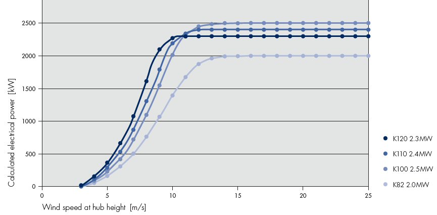
Kenersys (German/Indian) wind turbines
Electrical architecture
The problem
of converting from variable frequency AC power to fixed AC (60 hz) power
is handled by going from [AC to DC] then [DC to AC]. This is the standard
solution used in virtually all motor drives. When variable speed motors
are run off the power line the AC line power is converter to DC (stabilized
with capacitors) and then converter to AC at a frequency that depends on
the motor's speed. In a motor drive the conversion from AC to DC is relatively
simple because diodes can be used. In a wind turbine it's more complicated.
The generator needs its own IGBT controller which because its handing the
same power as the line-side IGBT converter is the same size. While this
is a good flexible solution for coupling two AC sources together it is
expensive in terms of power electronics. Two large electronic IGBT power
converters in cascade are needed as well as a large capacitor bank to stabilize
the DC link voltage.
Caveat -- Two converter coupled by a DC link are for sure used in a double fed induction machine, but in this machine only rotor power is handled by the converters, so the converter's peak power is about 30% of the turbine power.The DC link needs a large capacitor bank to stabilize it (uf is never specified). The DC voltage from the link capacitor is fed to line-side IGBT converter(s) that convert the DC to 60 hz AC (sinewave shaped and phase controlled) that connects to the 60 hz line via inductive filters (& transformer).PM generator converters, which have to handle 100% of the turbine power, might, or might not, use the same structure (it provides advantages). Clipper says the output of its PM generators is rectified. This may be a marketing simplification, or it might mean exactly what it says, that one of the converters is reduced to a six phase rectifier.
Double-fed
induction generator
I have yet to really figure out what a double-fed induction generator is,
but the Portuguese paper (on double fed induction generator) has a sketch
and a few tidbits.
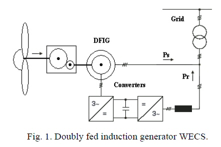
Induction stator power (Ps) is hard wired to 60 hz
grid
Induction rotor power (Pr) flows through two controller
and DC link to grid
Converter at 30% power
According
to the paper the double-fed induction generator has been used for a long
time in wind turbines.
It's big attraction is that the converter electronics
(bottom path in figure) typically only has to handle a maximum of 30% of
the power of the turbine. In other words where as a 2.5 Mw wind turbine
with a PM generator needed IGBT converters than can handle 2.5 Mw with
a double-fed induction machine the IGBT converter need only to handle 833
kw. This would be a substantial saving in electronics cost.
Double-fed induction generator is complex
It appears
in a double-fed induction generator that rotor winding is opened and brought
to the outside via the slip rings. So apparently the penalty for
lower power electronics is the turbine itself needs high power slip rings
that have to handle 30% of the turbine power! Also the rotor of this machine
must be very different than a normal induction machine. In a normal induction
machine heavy copper plates carry high current at very low voltage. To
feed the rotor power through the slip rings and to be able to handle it
in the electronics means that the rotor must be wound with lots of turns
to increase the voltage and decrease the current.
In short a double-fed induction generator is a complex specialized machine. Thus the trade for a much lower power rating on the electronics (about 1/3 rd the power rating that would be required with PM generator) is a substantially more complicated and perhaps less reliable generator.
Normal induction machine
In a normal
induction machine (motor or generator) the only power connection is to
the stator. The rotor is 'self powered' via changing magnetic fields (induction)
making the standard induction motor simple and rugged. It has no slip rings
or brushes. If the rotor rotates a little slower (typically 0 to 3%) than
the rate at which the stator magnetic field rotates, power flows into the
stator and out the shaft as mechanical power. It works as a motor. But
if the rotor rotates a little faster (typically 0 to 3%) than the
rate at which the stator magnetic field rotates, power flows into the shaft
as mechanical power and out of the stator. It works as a generator. This
change between motor/generator happens automatically as the rotor and stator
magnetic frequency cross.
My (initial) guess as to how it works
The Portuguese
paper seems to indicate that double-fed induction generator crossover frequency
is the middle of the rotor frequency range, saying that in normal operation
the slip goes +/- 30%, and in fact this is possible because the ratio of
(1+ 0.3)/(1-0.3) = 1.85, slightly above the speed range of the blades.
What bothers me about this, what apparently I don't understand, is that
even though the slip frequency is going positive and negative over the
blade frequency range the machine has to operate as a generator over the
whole range.
My guess is that when the current in the rotor can be controlled from the outside, what is done is that when the frequencies crossover the direction of the current is switched too. This may keep the machine working only as a generator at all frequencies. [Yup, see next]
The principle of operation --- or how a double fed
induction generator differs from a normal induction generator
Wikipedia
has a long article on the double fed induction machines (motors and generators).
It (indirectly) confirms my guess above is right:
A reversal of rotor current (and/or rotor power flow direction) reverses torque on the shaft and since [power = torque x speed] a flip of torque direction flips the machine between motoring and generating.In a normal induction machine the rotor speed can vary a little (3%) relative to synchronous speed, but this is of no use to a wind generator. One, the adjustable speed range must be kept low because rotor power is dissipated as heat on the rotor. Two, rotor speed can only be above synchronous speed, going below synchronous speed reverses the direction of torque and the machine becomes a motor pulling power from the line.
A double fed induction generator solves both problems. It brings out the rotor to the outside via slip rings (its achilles heel). Now the direction of the rotor current (hence torque) can be controlled, so the machine can be set to be a generator both above and below synchronous speed. Use of a controller allows the rotor power to be captured, so the slip range & rotor power can be greatly expanded (+/-30% slip).
Above synchronous speed captured rotor power is converted to 60 hz and added to stator power forming a second power path out of the generator to the line. Below synchronous speed a fraction of the stator power is bled off and fed back into the rotor. The controller converts the fed back power from 60 hz to the slip frequency. While in this mode the system is a little less efficient due to a power loop, but the extra losses are not a serious problem because at lower wind speeds the power to be processed is lower.
To make the controller and slip rings practical the rotor needs a lot of turns to increase the voltage and decrease the current. If slip is restricted to 30%, then the rotor probably has about 3x number of turns as the stator. Much higher turns and power flow in the rotor must mean that the rotor of a double fed induction machine is a lot bigger (bigger dia) than in a standard induction machine, which carries only a single shorted turn. (I have not seen a cross section to confirm this.)
Bottom line --- If (if!) the maintenance and (potential) reliability problems of the slip rings are acceptable, then a double fed induction generator is a good match to a wind turbine. To limit the slip (frequency) to +/- 30% requires that the speed range (max to min) of the blades be no more than [(1 + 0.3)/(1 - 0.3)] = 1.86, which (mirabile dictu) is what we find in wind turbines specs. The 30% slip limit means the controller only has to handle 30% of the peak power of the turbine, in contrast with a PM generator the controller has to handle 100% of the wind turbine power. Notice there are still more savings in power because rotor controller often operates below its maximum power. In the middle of the linear power range of the turbine, which is where the synchronous speed would be set, the controller power goes (virtually) to zero .
How
a double fed induction generator works in sketches
Here's some
engineering sketches (by me) showing how a double fed induction generator
works based on what I learned from the Wikipedia article (all text) and
the Portuguese paper:
Top sketch (above) -- Single fed induction generator
A standard induction motor is shown operating as a generator. In a standard induction machine operation as a generator only occurs when rotor frequency (speed) is above the synchronous frequency (frequency of the AC applied to the stator). Note mechanical power splits flowing to the stator and rotor. Power to the stator flows out to the line (useful work) and power to the rotor is dissipated at heat on the rotor (shown as a resistor in the sketch). The rotor power is typically small compared to stator power, but only because the slip frequency is typically very low (< 3%) in a standard induction machine.
Middle sketch (above) -- Double fed induction generator
In the middle sketch the frequencies are the same as in the top sketch, but now the induction motor is double fed. This is indicated on the sketch by the addition of the AC to AC converter. Essentially a double fed induction machine captures the fraction of mechanical energy that flows to the rotor and couples it to the line. Since rotor energy is now usefully recovered and not wasted as heat, it's practical to increase the slip frequency. The penalty paid as the slip increases is higher power rating on the AC to AC converter. Commercial double fed induction generators run with slips up to 30%.
Bottom sketch (above) -- Double fed induction generator below synchronous speedSo where does the power for the rotor come from? It comes from feeding back a fraction of the stator power. This is indicated in the sketch by the looping clockwise arrow. Power flowing in a loop means more losses, but note the character of the double fed machine fits well with the torque characteristics of a wind turbine. The less efficient circulating power mode occurs only in the lower half of the speed range where power is lower.
The bottom sketch shows flipping of the rotor current (power). Here the rotor frequency is less than synchronous speed. Under this condition a standard induction machine the machine would be operating as a motor (pulling power from the line), but here the AC to AC converter, which has bidirectional power flow capability, drives power into the rotor. The rotor power reversal flips the torque, so the system continues to operate as a generator even though rotor frequency is lower than synchronous frequency.
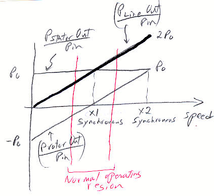
My sketch of the split of blade power (Pin) to stator
(Pstator) and rotor (Protor) vs speed
At low speeds rotor 'output' power is negative, because
power is actually flowing into the rotor
(circulating back from the stator)
Sketch (above) -- Rotor and stator power vs speed
In the sketch above I show the split of mechanical power between stator and rotor as a function of speed. At low speeds the stator and rotor powers nearly cancel because much of the power is looping. At (x1) synchronous speed slip frequency is zero, and at this speed and higher there is no circulating current. At x2 synchronous speed the power flowing out of the rotor is the equal to the power flowing out of the stator. This doubling of power is what (theoretically) makes a double fed machine a big improvement over a (standard) single fed machine.The red lines indicate that in practice a double fed system is only operated within the limited slip range shown by the red lines (-30% to + 30%). The range restriction is to reap the big cost advantage (and associated reduction in losses) of sizing the (rotor) controller at only 30% of the rating of the system.
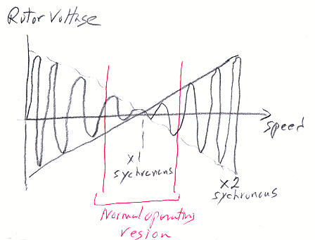
Sketch (above) -- Rotor voltage vs speed
The sketch above (by me) shows rotor voltage vs speed. Voltage = [d(flux)/dt], so if flux is constant voltage amplitude and frequency, as seen from the rotor, both linearly decline toward zero (on both sides of synchronous speed, as shown) becoming DC at synchronous speed. Power = [current x voltage], so if the rotor torque current is constant, the linearly declining rotor voltage causes the rotor power to linearly decrease toward zero at null. It is correct to say at a slip frequency of 30% (with the rotor voltage only 30% of the stator voltage assuming same number of turns) the rotor converter is handling only 30% of the power of the stator.From the rotor viewpoint the difference between standard and rotor fed induction machines can be more easily understood . In a standard induction machine when the rotor frequency goes through null, i.e. from one side of synchronous speed to the other, the rotor voltage flips polarity, and since the rotor voltage controls the current [i = v/Z], the rotor current polarity also flips. It is the reversal in rotor current polarity at synchronous speed that reverses the direction of machine torque and that flips the mode of the machine (motoring or generating).
In contrast in a rotor driven induction machine the rotor current is not controlled by the rotor voltage, but by the rotor converter. It can and is held constant through null, so the machine torque, and hence machine mode (motoring or generating), does not change going through null. But the reversal in rotor voltage at null (coupled with no change in rotor current) does reverse the direction of power flow in the rotor converter. In a double-fed induction generator above synchronous speed power flows out of the rotor, and below synchronous speed power flows into the rotor (being looped back from the stator).
Wikipedia on double fed induction generators (Wikipedia -- Doubly-fed electric machine)
-- Typical applications of doubly fed machines have been high power pumps and fans, hydro and wind generators, shaft generators for ships etc where operating speed range has been quite narrow, less than ± 30 % of the synchronous speed and only small power is required in the subsynchronous range. These are applications where the efficiency and low cost power electronics outweigh the reliability issues associated with the slip ring assembly.-- A multiphase slip ring assembly (i.e., sliding electrical contacts) is traditionally used to transfer power to the rotating (moving) winding set and to allow independent control of the rotor winding set. The slip ring assembly requires maintenance and compromises system reliability, cost and efficiency. Attempts to avoid the slip ring assembly are constantly being researched with limited success.
--Half the world's leading manuf of wind turbines use double-fed induction generators. Many double fed patents are assigned to ABB (Finland and US)
-- At subsynchronous speeds the stator is generating the power but part of it has to be fed back to rotor. At supersynchronous speeds both the rotor and stator are producing power to the grid.
-- The doubly-fed generator rotors are typically wound with from 2 to 3 times the number of turns of the stator. Voltage transients due to the grid disturbances are magnified, so to prevent high rotor voltages and current from destroying the IGBTs and diodes of the converter a protection circuit (called a crowbar) is used.
-- Doubly-fed electric machines outperform the other types of machines in supersynchronous speeds. They can operate at constant torque to twice synchronous speed if each active winding is rated at half the total power of the machine. Doubly fed machines do not produce more rated torque per volume than singly fed machines. The bigger power rating is due to the higher speed attainable without weakening the magnetic flux.ABB wind turbine induction & PM generators-- Conclusion: The wound-rotor doubly-fed electric machine incorporates the most optimum electromagnetic design of any electric machine, but requires a slip ring assembly which is its Achilles' Heel.
ABB preventive maintenance brochure recommended replacement interval:
Slip rings (carbon brush)
1 yr
Grounding (carbon brush)
1 yr
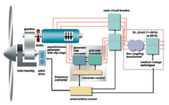
ABB wind turbine block diagram with double fed induction
generator
Shows: three rotor slip rings, three breakers, coupling
transformer
PM generators
ABB says their PM
(NdFeB -- Neodymium Iron Boron magnets) generators compared to double fed
induction are: smaller, more efficient, cooler running and less maintenance.
Clipper argues that PM generators have another and pretty obscure advantage.
In the event of an electrical fault (short) on the line the generator will
brake the gearbox hard and it might be damaged. For this reason a (breakable)
coupling may be needed between the gearbox and generator, but the Clipper
says their PM generator(s) have a low enough short circuit current (&
torque) that no protective coupling is needed.
Clipper says in their 2.5 Mw turbine the PM generator outputs are rectified to DC, then chopped to AC by (high capacity) IGBT's. Only one converter? Maybe. If the generator output is rectified then DC, then bus voltage is going to vary a lot (x1.7), but if the PM generator were driven by second controller, then the DC bus voltage would be stabilized.
Double fed induction generator
PM generator
----------------------------------------
------------------
Power
1.5 to 5 Mw
2 to 5 Mw
Speed
1,000 to 1,500 rpm (4 to 6 poles)
1,000 to 2,000 rpm (4 to 8 poles)
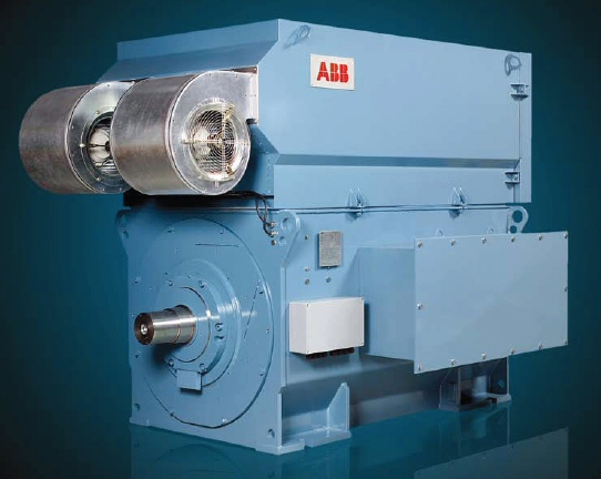
ABB double-fed induction generator (1.5 to 5 Mw
)
Induction generator start weirdness
I worked on
induction generators thirty years ago. In fact I even co-hold a patent
for a control technique for induction generators.
Patent
#4,417,194 Induction generator system with switched capacitor
control
Inventors: Curtiss and Fulton, Issued Nov 1983
A stand alone (or offline) induction generator has a weird problem. It does not reliably start! The shaft can be spinning, yet no voltage and current may come out. This is totally unlike a PM generator. When you spin a PM you get a voltage, it's a law of nature. But in an induction machine there are no PM's, it works like an electromagnet. To get an induction generator to start working you need an outside source to put in a little current to make a magnetic field. Once the generator action starts it's self sustaining because the power generated can easily keep up the magnetic flux within the generator.
I remember reading (way back when) a paper arguing that for this reason induction generators would never be practical. Even used as part of electrical grid there is the problem of how to restart the grid after a blackout when lots of induction generators on the grid each need to be excited, and before an induction generator starts it puts a relatively heavy load on the grid.
To date I have
seen nothing about how this problem is addressed in modern wind farms.
One solution would be to have a central controller be able to disconnect
and reconnect turbines, and then it could restart them one at a time. Wind
turbines can go off line in high winds too, so a restart procedure must
be part of wind farm planning. My guess is that each there must be a (remotely
controlled) breaker in each nacelle to take a generator offline, both for
maintenance and to aid restart.
High capacity IGBT's
In mid 2008
Fuji announced high capacity IGBT's specifically targeted at controllers
for wind turbines.
1200 V
1700 V
600 A - 3,600 A
600 A - 3,600 A
1200V/1700V available in six current ratings: 600A, 800A, 1200A, 1600A, 2400A, 3600A
Package sizes
1600 A dual
13 cm x 14 cm (5.1 in x 5.5 in)
3600 A single
19 cm x 14 cm (7.5 in x 5.5 in)
These packages are amazingly small for this power. Ten years ago the state of the art for IGBT duals was 300A/1200V. The top terminals in pictures looks awfully small for these huge currents. Thermally these packages will pour out the heat into flowing liquid. The forward voltage is about 2.0V, so DC losses at rated current are [3,600 A x 2V] = 7,200 watt.
7,200 watt is the equivalent of almost five 1,500 watt room heater coming out of a surface area of 7.5 in x 5.5 in! But this is a test condition. In a real inverter for a 2.5 Mw turbine it's more like from each of six modules [1894 A x 1.8V x2 (two paths) x 2 (switching loss = static loss) x 1/6 (symmetry)] = 2,300 watt.
http://www.fujielectric.com/company/tech/pdf/r52-2/03.pdf
Example --- Clipper 2.5 Mw turbine (PM generators) DC link is 1,320 VDC at rated power
2,500 kw/1.32 kv = 1,894 A
A single converter using six 2,400 A (or 3,600 A), 1,700 V IGBT's could handle the 2.5 Mw from the PM generators. (Based on my snubbing experience with high current IGBT's two matched paralleled 1600 A duals might be a better choice because duals are easier to snub.)
Cost
comparison to 1,000 Mw nuclear plant
A 2.5 Mw wind
turbine operating at 30% capacity outputs 0.75 Mw average output. This
means it takes [1,000 Mw/0.75 Mw] = 1,333 2.5 Mw wind turbines to have
the same average power output as a standard 1,000 Mw nuclear plant!
Even then they are not a useful as baseload nuclear plant because the power
is variable. With these values we can construct a cost table
If 2.5 Mw turbine costs 1 million, then 1,333 turbines costs 1.3 billion
If 2.5 Mw turbine costs 3 million, then 1,333 turbines costs 4.0 billion
If 2.5 Mw turbine costs 5.9 million, then 1,333 turbines costs 7.9 billion
Dec 2009 figures from a very large wind farm (338 2.5 Mw GE turbines) to be built in Oregon (2010 to 2012) is 4.1 million per 2.5 Mw turbine paid to GE (1.4 billion contract) with installed cost per 2.5 Mw turbine of 5.9 million.
For comparison in 2008 South Carolina Electric and Gas Co contracted to buy two 1.12 Gw nuclear reactors (model AP 1,000) for 9.8 billion. This is the equiv of 9.8/(2 x 1.12) = 4.4 billion for 1,000 Mw plant.
So it looks like wind power raw upfront costs are about x1.8 nuclear (7.9 billion vs 4.4 billion for 1,000 Mw average).
How much wind power installed in USA?
In the USA,
even though we have more wind turbines installed than any other country,
we get only 1.25% (another source says 2.5%) of our electricity from wind.
Really, from the business press (4/09):
U.S. installed wind generation is 25.3 Gw (equiv of about 10,000 2.5 Mw giant turbines!), up a factor of two in last two years. Last year 42 % of all new generating capacity installed in the U.S was wind. Texas and Iowa have the most wind generation, followed by California and Minnesota. Minnesota gets 7.5 % of its electricity from wind (highest percentage in US).Now 25.3 Gw installed (peak, of course, because these numbers come from the Wind industry) at 30% capacity is 7.5 Gw average. The US total electric generation capability is just about [1,000 x 1,000 Mw (eq) plants] = 1,000 Gw. So putting two and two together I suspect the US is really only getting (as of 2009) about [7.5 Gw/1,000 Gw] = 0.75% of its electricity from wind. The claims for 1.25% to 2.5% of electricity from wind looks to me like wind's peak power rating being compared to the (continuous) baseload rating rating of coal, nuclear, and hydro power plants.
.
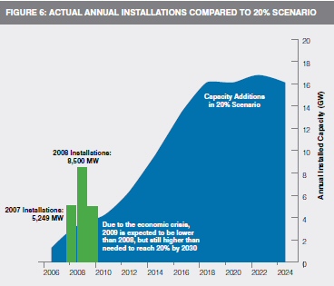
annual GW install for wind to be 20% of USA electricity by 2030
green is actual install (roughly 200 GW needed by 2030)
10.0 GW were installed in 2009 (35 GW total)
5.5 GW installed in 2010 (40 GW total)
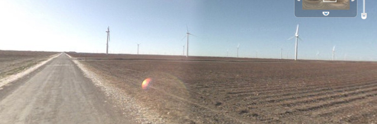
Wind turbine disasters
There's a whole bunch of YouTube videos showing failed wind turbines. The
failures include: fires, structural failures, and spectacular collapses
as blade speed gets too high (failed pitch and failed brakes). (It could
be that the overspeed video's are really overspeed tests done by the engineers.)
To put these failures in perspective there are over 10,000 wind turbines
in just the USA.
http://www.youtube.com/watch?v=ppLh5pGX3qQ&NR=1
(lots of pictures)
http://www.youtube.com/watch?v=QL-cRuYAxg0&feature=related
(overspeed collapse)
http://www.youtube.com/watch?v=lvvRHhsQhi8&feature=related
(slow motion of collapse)
Gallery
-- June 2006
Spain's Gamesa Group opened its US 50 million, 183,000 sq.- ft. fiber blade
LLC wind turbine blade operation in Ebensburg, Pa. The plant, which employs
205 but could employ 235 in a few years, will have the capacity to turn
out enough blades to produce 300 megawatts every year.
Below is truly enormous, a 2.5 Mw Nordex (Gamesa) model N90/2300. Dia of blades is 90m (295 ft) or virtually one football field! Tower height is 80m (230 ft) eq to 23 story building.
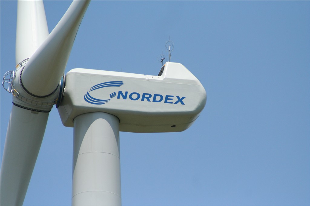
Nordex 2.5 Mw
Nordex generator is double-fed asynchronous
Manuf: Gamesa (Spanish) in Ebensburgh PA
location: Blue Knob Ridge, PA
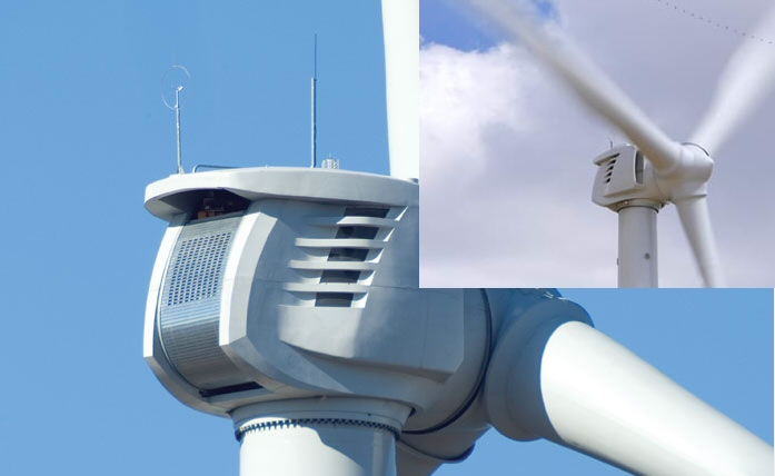
Clipper 2.5 Mw
Clipper generator is PM
The 2.5 Mw Clipper uses a PM generator (actually four small ones in parallel) whereas the Nordex 2.5 Mw uses a double-fed induction generator. Is this why the Clipper nacelle looks so much smaller than the longer Nordex? The Clipper nacelle is more open to the outside, probably for air cooling, than the Nordex.
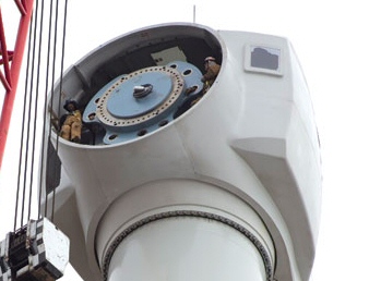
Clipper 2.5 Mw with men in nacelle
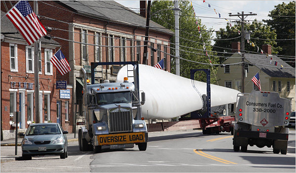
single blade (shipped in from Denmark or Vietnam)
being trucked thru Seaport ME
(Update 10/11)
Recently saw my first wind turbine blade on a truck. Unbelievably huge! Passed a truck convoy of three wind turbine blades headed north on Rt 95 in NH (toward ME), each blade carried by a special extended truck. I have never see a big wind turbine, but could imagine how it must be looking at these blades.
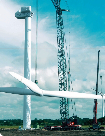
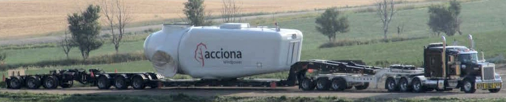
Acciona nacelle on truck
(BK Trucking site)
Nice video showing construction of a large turbine in Danforth Maine (Stetson Wind) starting with building the foundation.
http://www.firstwind.com/media_center/Wind_Turbines_Local_economic_stimulus
Stetson Wind in Danforth Maine, run by First Wind (Boston) is the largest wind farm in Maine. It now consists of 38 1.5 Mw GE wind turbines (57 Mw total) and went operational Jan 2009. They are building another 17 turbines (55 total turbines), which will bring the total rated power to 82.5 Mw. But when 30% capacity is figured in the total average power from all 55 turbines is 25 Mw, so the whole wind farm is equivalent to 2 to 3% of a standard 1,000 Mw (nuclear) baseload plant! (pretty discouraging)
First Wind has about 18 wind projects going in five states, six of which are operational (478 Mw). Biggest by far is Utah where 200 Mw are operational and another 800 Mw (four 200 Mw farms) are in the planning stage. The operational Utah farm is 97 turbines (58 Clipper Liberty 2.5 Mw and 39 GE 1.5 Mw). 65 million was spend on the Stetson farm (about 1.7 million for 38 towers). 40 million for the Stetson project come from US taxpayers in the form a Tarp grants. The company has announced getting 115 million in grants! The company has raised about 230 million in private capital (from private equity groups).
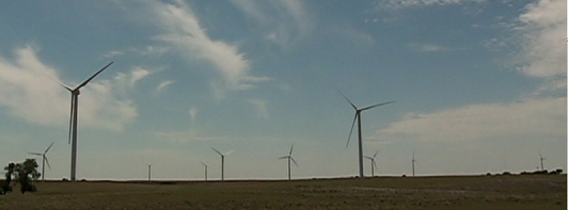
wind farm Kansas (?)
(screen capture from BK Trucking TV show)
Wind Subsidies
Oh, yes! Economist
magazine says a wind farm owner in US gets a check for 30% of the cost
of the farm from government when it goes on line. This is correct. It is
part of the stimulus package (American Recovery and Reinvestment Act) and
is providing huge grants to companies like First Wind. There was, or probably
still is, also an income tax credit of 2.1 cents for each Kwh from a wind
turbine.
Lightning
First Liberty
Clipper operating since 2005 has been hit by lightning four times (about
once a year). Three time no damage, but minor damage to blade tip (repaired)
on 4th strike. NYT writes about robe climbers are now often used to inspect
or repair lightning damaged blades, cheaper than bringing in cranes or
sky buckets.
"After vanishing up the tower, the two climbers appeared as tiny specks at the top of the turbine. Each was secured to the top by two ropes. They let themselves slowly down the (fiberglass) blade, which was pointed toward the ground, and got to work. An orange extension cord, over 150 feet long, accompanied them, to power the sander."Wind turbine technology
huge blades
huge gearbox (except for Enercon)
huge generator
huge inverter electronics (smaller with double fed induction generator)
all held aloft by a very tall tower that is strong enough to hold the tremendous weight to survive the worst hurricane winds.
Wind turbine
manufacturers (2009)
-- Six of
the top 10 global utility-scale wind turbine manufacturers have a manufacturing
presence in the U.S., according to the AWEA: General Electric, Vestas,
Gamesa, Suzlon, Siemens and Acciona.
-- GE Energy is the largest supplier of wind turbines in the U.S., accounting for 43 percent of all new wind power capacity installed in the country last year, the AWEA said. The company imports many components, including blades, but also sources extensively in the U.S. and has opened three domestic manufacturing facilities, including the wind turbine plant in South Carolina, another turbine manufacturing plant in Tehachapi, Calif., and a generator plant in Pensacola, Fla.
-- Vestas ranked No. 2 in 2008 U.S. installations, at 13 percent. The worlds second-largest turbine maker after GE, Vestas is basing a fast-growing U.S. manufacturing presence in Colorado. In March, the Danish company broke ground on two new factories in Brighton, Colo., a wind turbine blade factory and a nacelle assembly plant valued together at $290 million.
-- US leads the world in installed wind capacity and new turbine installations, the AWEA said. Last years 8,500 megawatts of new wind power capacity brought the nations total to more than 25,300 megawatts, and surpassed longtime leader Germany. Texas alone comprises the worlds sixth-biggest wind energy market. In 2008, the state added 2,671 megawatts, more new capacity than any country except China and the rest of the U.S.
-- Wind industry supplied 1.25 percent of the U.S.s electricity in 2008.
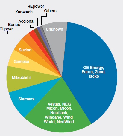
Installed USA Mw pic chart
Wind turbine history
25% (6.9 Gw
peak) of all US wind power capacity is owned by NextEra Energy Resources
(they own nuclear and gas plants too). They have about 65 wind farms all
over the US, and their site has a link for each farm telling what turbines
are installed and when they were installed. I paged through them.
Here's a summary:
1986
150 kw Danwin
(Netherlands?)
1991
100 kw? Kenetech (USA)
1994
365 kw KVS
1986?
600 kw Mitsubishi (Japan)
2001
660 kw Vesta V-47 (Denmark)
1999
750 kw NEG Micron (German)
2000
750 kw Zond (USA)
2000
1.3 Mw Nordex N60 (German)
2001
1.3 Mw Bonus (German)
2003
1.8 Mw Vesta (Denmark)
2005
1.5 Mw GE (USA)
2008
1.5 Mw GE (USA)
2005
2.3 Mw Siemens (German)
(Horse Hollow Tx, 735 Mw farm)
2008
2.5 Mw Clipper (USA)
Missing from the above list is the major manuf Enercon (German), because they lost a patent fight and were forbidden from selling in US until 2010.
http://www.nexteraenergyresources.com/content/where/portfolio.shtml
http://www.nexteraenergyresources.com/content/where/portfolio/pdf/portfolio_by_fuel.pdf
** Database of all world wind turbines (ratings, manuf,
specs)
http://www.thewindpower.net/213-wind-turbine-ranges.php?tri=2
In a 2001 paper ABB described the technology of the biggest models of the eight largest wind turbine manuf. As of 2000 power levels were 1 to 2 Mw and most of them (6 of 8) were already using the dominant technology of today: variable pitch and variable speed. Two were dual fixed speeds (NEG Micron and Bonus). Five of the six variable speed used a gearbox, but interestingly one (Enercon) was gearless (10 to 24 rpm) at a power level of 1.8 Mw. So what is it that is new in the 2.2 Mw direct drive unit that Northern is developing?
http://www.scribd.com/doc/8637081/eolica-Generators-Power-Electronics-for-Wind-T
History
-- In 1988
Electric Power Research Institute US Windpower consortium (assisted by
Charlie Smith of Electrotek) started working on variable speed wind technology,
the consortium evolving into Kenetech. In late 1990's Kenetech goes bankrupt.
Zond acquired Kenetech variable power electronics technology, and this
allowed Zond to offer a viable variable-speed product in the commercial
market
* Zond starts 1986 using Vesta turbines, later (with government funding) develops their own technology. In 1997 Zond partially sold to Enron. Enron buys bankrupt German turbine manuf Tacke and Zond and Tacke technology combined develop successful 1.5 Mw turbine. In 2002 Enron goes bankrupt and GE sweeps buying Zond/Tache forming GE Wind. GE Wind is now biggest US wind company.
* Founder of Zond (Dehlsen) leaves to start Clipper in 2003. First (& to date only) product is a 2.5 Mw turbine. After two years in field their 2.5 Mw turbines develop bad blade problems costing them 300 million (one million a turbine!) to fix. Clipper is planning a huge 5 Gw farm in South Dakota (5 or 6 years away, no transmission line)
* T. Boone Pickens proposed world's largest wind farm (2007/8 now cancelled). It was to be 4 Gw (eq to 1,600 2.5 Mw turbines) located in Texas panhandle. Transmission line delays. Boone had already ordered 687 turbines from GE.
Technical history
-- Zond/Enron
Wind products after they acquired the Kenetech patents in the bankruptcy
proceedings, and now is a kernel of GE Wind's products.
-- I think the basic variable-speed wind patent should never have been granted because significant prior art dating back to the 1970s existed. Deep down, I wish power-electronic variable-speed wind were in the pubic domain so that all could use it. However, if that were the case, it's possible that without that piece of significant intellectual property GE may not have been as likely to re-enter the wind business.
-- Understanding and quantifying the structural loads was a breakthrough that probably covered a 10-year span. This was the gate we needed to pass through to substantially scale up machine size, overall the greatest contributor to the reduction in COE. By defining appropriate levels of structural loads, the International Design Standards firmed up, which in turn broadened wind project financing sources. In a similar way, the availability of test facilities, most notably the NREL drive train and blade test facilities, has led to refinements in design and comfort to the financial community on which wind expansion depends.
-- Modern wind turbines are designed to spin at varying speeds (a consequence of their generator design, see above). Use of aluminium and composites in their blades has contributed to low rotational inertia, which means that newer wind turbines can accelerate quickly if the winds pick up, keeping the tip speed ratio more nearly constant. Operating closer to their optimal tip speed ratio during energetic gusts of wind allows wind turbines to improve energy capture from sudden gusts that are typical in urban settings.
-- In contrast, older style wind turbines were designed with heavier steel blades, which have higher inertia, and rotated at speeds governed by the AC frequency of the power lines. The high inertia buffered the changes in rotation speed and thus made power output more stable.
-- Wind turbines developed over the last 50 years have almost universally used either two or three blades. While aligning the wind turbine to changes in wind direction (yawing), each blade experiences a cyclic load at its root end depending on blade position. This is true of one, two, three blades or more. However, these cyclic loads when combined together at the drive train shaft are symmetrically balanced for three blades, yielding smoother operation during turbine yaw. Finally, aesthetics can be considered a factor in that some people find that the three-bladed rotor is more pleasing to look at than a one- or two-bladed rotor.
-- NASA did a lot of work on wind power in the early days. The 98 meter diameter, two-bladed NASA/DOE Mod-5B wind turbine was the largest operating wind turbine in the world in the early 1990s. An early CA wind farm was also either built by NASA or using a NASA designed turbine.
-- Wind shear refers to the fact that wind speed goes up with height. This is true because winds near the surface experience a friction drag. The 'Wind profile power law' shows the wind velocity at 50 m is x1.26 higher than at 10m. The reason towers are so tall (besides long blades!) is that [1.26^3] =2, so there is twice as much power in the wind at 50 m compared to 10 m.
Blade testing in Charlestown
Government
is funding a blade certification facility to be built in Charlestown (old
Navy Yard?). News stories say it can test blades up to 90 m in length.
I first thought this couldn't be right since they test single blades, and
rotor dia on even on offshore huge turbines are in the range of 110 to
120 m, but apparently it is right. Here's a link with the blade testing
specs and sketches of the facility. They broke ground Dec 09 and expect
to build it in about a year.
http://www.masstech.org/wttc/wttcfinal.pdf.
Chinese wind power (12/15/10)
China is now
a major wind turbine player. According to NYT they acquired much of their
technology from Spain's Gamesa by requiring most components to be built
in China. Gamesa at that time had 50% of Chinese market and sent scores
of engineers to China to teach them how to build components, now Gamesa
has only 3% of the Chinese market. In 2010 china has installed 17.6 Gw
of wind (highest in world) mostly Chinese built turbines vs 5.5 Gw in USA.
Front page story today in NYT is about the first three Chinese designed wind turbines (by GoldWind) installed in US. GoldWind has opened an office in USA for a major push into US market. Cielo Wind Power is planning a 0.6 Gw, 1.5 billion wind farm in West Texas (36,000 acres, 7 mi x 7 mi, turbines about 1/2 mile apart) using 240 2.5 Mw turbines made in China by A-Power Energy Generation Systems, however some of the turbine will be from Germany and the gearbox from GE.
Local wind
MA like CA has passed
a low mandating that utilities increase their share of power from renewables.
Under state law 25 percent of power must come from renewables by 2030.
As far as I know, as of 2010, virtually zero MA electricity comes from
renewables. The first big project to come on line will be Cape Wind (now
approved) with 130 turbines.
1.5
Mw Chinese turbine goes up near Boston (Nov 2011)
Software theft alleged (update 3/21/12)
Bloomberg
magazine has a long article that makes a strong case the Sinovel, manuf
of the Boston turbine, is operating its turbines with stolen code (from
AMSC, a company in MA no less). AMSC was selling them 200 million a year
worth of electronics, which appears to include the inverter made by AMSC
in China as well as software for control of the turbine, and a year ago
sales stopped entirely.
"Sinovel, however, was caught red-handed. AMSC has presented to law enforcement officials in Austria and China computer logs and messages that show Sinovel courting one of the U.S. companys employees and paying him to aid in the code heist. Its a red-hot smoking gun example, said John Kerry, chairman of the Senate Foreign Relations Committee and the Democratic U.S. senator from AMSCs home state."The Boston turbine is still just sitting there, not rotating with its blades feathered. A search turns up a Feb 2012 article in Boston Hereld that gives the reason. The turbine has been shut down because its foundation is not stable, it's slowly sinking (two inches so far). Not too surprising as this is filled land. The fix is expected to be injecting grouting to strengthen the ground. A poster to this article provides some very interesting background.
"MWRA communications director Ria Convery says the agency used $4.7m from the 2009 American Recovery and Reinvestment Act to buy the turbine, and an installation contract was awarded to Solaya, which chose Sinovel, partly because the electrical control systems were made by Massachusetts-based AMSC.
MWRA had to obtain a waiver for the buy American clause in the economic stimulus law.
AMSC cut its business ties with Sinovel after alleging that the Chinese turbine giant had stolen its intellectual property. Convery acknowledges the rift, but the state did not reconsider the deal."Poster also says that three more Sinovel 1.5 Mw turbines have been bought and will be going up in two location south of Boston.
Quality problems? (update 3/6/12, 4/25/12) (8/15/12)
For
the last six weeks or so the Boston Chinese turbine has not been rotating,
its blades feathered. I had seen one reference in the press to Sinovel
having quality problems with their turbines, I'm beginning to think there
is something to that. Also it's taking forever to get it repaired.
The problem with the 1.5Mw Everett turbine is reported to be the ground under the wind turbine, which I think is likely filled land, is settling. The tipping is not large, a factor of two out of spec, something like tipping of two inches vs allowed one inch. I read nearly two months ago that the fix would be groat injections into the ground to stabilize it.
(4/25/12
update) Everett wind turbine is still not rotating. Yikes! How long is
this going to take?
(8/15/12
- 21 update) Everett wind turbine has finally started again to rotate.
It was down seven months!!
And less than 2 weeks after restart, it's down again!
------------------------------------------------
Sinovel, who
is Chinas largest wind turbine manufacturer, is going to be providing
a 1.5 Mw turbine, for a Charlestown waste water pumping station. A large
local turbine! I was unable to find any information about where it was
going, but when it went up, I found it was in my old hometown (Everett),
easily visible from Rt 93 highway just north of Boston.
The 1.5 Mw turbine went up in Oct 2011 in Everett, near the Boston Everett line across the street from the large Everett Edison 'Mystic' power station. Normally a turbine manuf puts his name on the nacelle, but here the name is MWRA (Mass water authority). There was virtually no mention in the PR from this state agency that they had gone to China to buy a wind turbine. The full 4.7 million cost was provided the the US taxpayer (via Federal program). Here are photos I took of it.
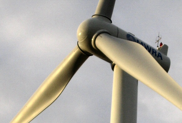
1.5 Mw Sinovel turbine installed by MWRA in Everett
rotation: clockwise (narrow edge is trailing), rotating
fairly slowly (3-4 secs/rotation)
thing sticking up at the far end of the nacelle is
an air sensor (speed and direction)
photo credit: Don Fulton
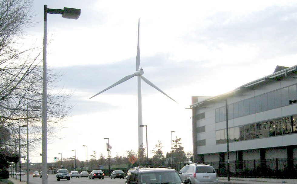
1.5 Mw Sinovel turbine Everett Ma (close to Everett
- Charlestown town line)
photo credit: Don Fulton
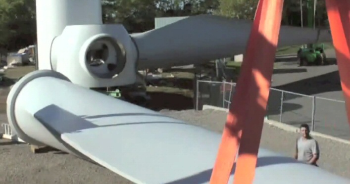
one blade of 1.5 MW Sonovel Everett turbine (MWRA
video capture)
Estimate blade width at widest point (near man) about
10-12 feet
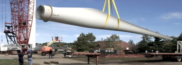
one blade of 1.5 MW Sonovel Everett turbine (MWRA
video capture)
If width at bulge is 10-12 feet, then near tip blade
width is only 2-3 feet.
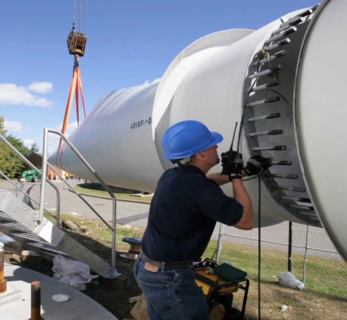
blade's ring of long bolts mount in holes in large
dia gear in hub
(nice way to get your hand crushed) (MWRA video capture)
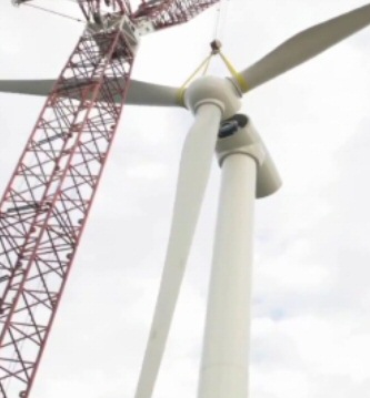
blade mount 1.5 MW Sonovel Everett turbine (MWRA video
capture)
note blades all rotated 90 degrees
MWRA has put on YouTube a nice HR 6 min video of this particular wind turbine being installed using one monster crane assisted by a much smaller crane. A screen capture from the video shows clearly the shape of the blade.
http://www.youtube.com/watch?v=tjATpb6hr7A
Local wind (update 10/24/11)
This summer
passed three super long trucks stopped on side of highway each carrying
one turbine blade. Even speeding past at highway speed the blades looked
huge.
This week, the Charlestown Wind Turbine, the first (relatively) big wind turbine (1.5 Mw) anywhere near me, has quickly gone up and a few days later was rotating. It is easily seen from Rt 93 elevated highway just north of Boston. It is located somewhere near the bridge between Everett and Boston and near the Schrafft Center in Charlestown, where I used to work. It has been put up by the state water people (MWRA, Mass Water Resources Authority).
It cost 4.7 million, bought with federal stimulus money. Zero mention in the press that the state went to China to buy a wind turbine! Usually wind turbine nacelles are marked on the side with the manuf name, but this one is marked with its owner's name: MWRA. In fact it took a lot of searching to find the manufacturer, just one line saying that it was "installed" (not manufactured) by Sinovel.
Sinovel 1.5 Mw turbine
Sinovel web
site shows they make four 1.5 Mw wind turbines with different blades sizes
(60 m to 83 m dia). The larger blade turbines hit full power at lower wind
speeds (10.5 m/sec) vs the smaller blade (14 m/sec). No info on model number,
but the press releases do give the height (364 ft). Press reports say it
is expected to produce 3 million Kwh. Not clear if this is the manuf spec,
or the number for wind at this site. I doubt this site is particularly
windy as it is a mile or more up river from the ocean.
3 Mkwh/(8,766 hr/yr) = 342 kw average power (23% of peak power)
Spec shows (min) hub height 65m (213 ft). This would give a blade dia of 2 x (364 ft - 213 hub height) = 302 ft (92 m) too big, the biggest blade dia in specs is 82.9 m. But it is a good guess that this their largest bladed turbine (model SL 1500/82) as I expect the wind dia there is low. The large blade model is spec at full power (1.5 Mw) at 10.5 m/sec (23 mph). Min speed is 3 m/sec (6.6 mph).
http://www.thewindpower.net/turbine_technical_en_281_sinovel_sl-1500-82.php
http://www.sinovel.com/en/procducts.aspx?ID=150
50% Efficiency Mystery
Well it's
a mystery to me, not the wind turbine designers, as to how three narrow
blades can capture about 50% of the kinetic energy passing through the
blade circle. The best data for this is from Enercon wind turbines (below).
Along with power vs air speed, they plot the turbine 'power coefficient',
which equations show is the multiplier of the kinetic energy contained
in a cylinder of air with dia of the blade circle and extending back the
distance air flows in one second (see my sketch above).
Look at the pictures of the 1.5 Mw Sinovel turbine (above). Probably 95% of the blade area is open! A simple calculation shows half the incoming cylinder of air (dia equal to the blade dia) is a ring in the outer 30% of the radius and look at how incredibly narrow the outer part of the blade is. The large flaring section of the blade is about 1/3rd (or a little more) down the blade from the hub.
Blade as airfoil
Since the
blade speed is controlled at the end to be about x7 wind speed, it means
from the blade point of view nearly all the blade (6/7th) sees an airsteam
flowing into the blunt edge and out over the tapered (trailing) edge. Rotation,
not wind direction, dominates the air flow over the blades.
Think of sitting in an airplane and looking out at the right wing. It has an airfoil shaped tiled upward, blunt edge facing forward, tapered edge trailing. Suppose the airplane left wing was like the right wing only flipped over (blunt edge still front). Now consider the plane flying foward. What happens? Force on the right wing is (initially) upward (as normal) and force on the left wing is downward (this wing tilts downward in front). The plane body is now like the hub of a two bladed rotating turbine (sans load) it will rotate! At all orientations the force on the two wings remains opposite maintaining the rotational torque.
Force on an airfoil
The NASA site
in the reference (How planes really fly) argues that forces on objects
inserted into flowing fluids is an opposite reaction (Newton) to how the
fluid flow is bent. In other words the upward tilt and airfoil shape
of an airplane wing (both top and bottom surfaces acting indendently) bends
(to some degree) the air flow downward. Hence by an equal and opposite
reaction the downward deflected air exerts an upward force on the wing.
This is how airplanes really fly.
How
blade 'airfoil' is driven forward
The 1999 sketch
below from a turbine manuf shows the basics of how the blade airfoil is
driven forward by the wind. At first I thought the force vectors (C) right
were wrong, but I now understand it is correct. This figure provides a
qualitative
picture of blade airfoil lift and rotation. Well, qualitative is a start
...
Here is what the sketches figure below represent. The blade shown is understood to be crosssection near the tip of the blade. The turbine blade in normal operation rotates (rightward, blunt forward) in the 'plane of rotation'. The wind speed and dirction (think fairly high wind, 10 m/sec) is indicated by the arrow 'v'. The turbine is normally oriented into the wind, so its blade rotation plane is perpendicular to the wind. Note the blade is (almost) flat to the wind, 0 degree oriention, which agrees with what I see when I look at the blade orientation of the big local turbine.
In the 'A' sketch the wind 'v' is blowing, but turbine is not rotating. (This is just for example, but does represent real world condition of the wind just starting to blow.) The direction of force 'F' vector on the stationary (narrow) blade is in the wind direction and toward pushes the blade toward the tower. No real motion or power transmitted here, just a little blade flex into the tower.
In the 'B' sketch the turbine is up to speed with the wind 'v' unchanged, and the blade is moving right along 'plane of rotation'. Notice that the 'B' sketch shows the 'in your face' wind component 'u' caused by the blade rotation is many times bigger than 'v' (and it's really much bigger than drawn. It is not to scale). This is correct as the tip speed of most modern large turbines is controlled to be x7 wind speed. The air flow the blade 'sees' is sort of a local wind and is the vector sum of the (external) wind 'v' and the much larger induced (in your face) wind 'u', shown on the sketch as 'w'.
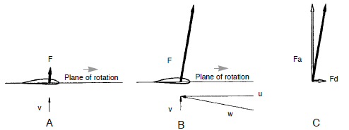
A not rotating, B rotating, C forces on rotating blade
(A vs B,C not to scale)
'v' = wind, 'u' = blade wind due to rotation
'w' = vector combined 'wind' seen by airfoil
source -- http://www.windmission.dk/workshop/BonusTurbine.pdf
Nice figure showing turbine airfoil lift vectors from Makani Power.
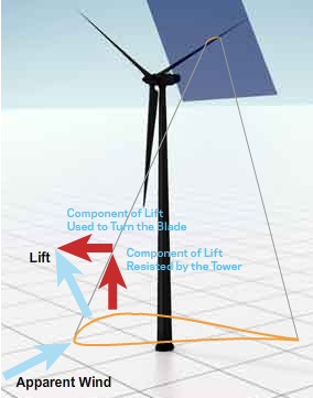
source -- http://www.makanipower.com
Blade lift and
rotation
The
key is to understand turbine rotation is to understand the (net) force
on the blade ('F'), and how it can be resolved into two orthogonal components,
one in the direction of rotation (Fd) and one in the direction of the tower
(Fa). I at first thought the force vectors were drawn incorrect (rotated),
but they are correct. Next I will explain why they are correct, but if
we accept them as correct for a minute, look at what they interestingly
show.
First big surprise is that the really big component of the force (Fa) is toward the tower, basically a blade flex term. And note this non-power, toward the tower force ('Fa') grows as the blades rotate faster dwarfing (x36 to x49 larger!) the force the wind would put on the narrow turbine bladed not rotating. Second, we can see that it is the small force term (Fd) that actually causes the blade to rotate. Note this force term points rightward in the plane of rotation, which is the rotation direction assumed when in your face 'u' wind vector was drawn. But note 'Fd' is not really that small, it is only small relative to the very large bending force 'Fa' on the blade.
Here is the key -- two wind terms set angle of attackLying on the blade
While the turbine blades are oriented (virtually) flat to the incoming wind (which intuitively seems wrong, but it's not), the blade airfoil by virtue of its high speed motion around the blade circle sees air coming pretty much at its blunt (right) edge. But look at the net local wind seen by the airfoil (w') in the 'B' sketch. The local wind seen by the airfoil is actually coming in (and hitting it) from below at an angle of about 8 (inverse tan of 1/7).The blade is working (in some ways) like an airplane wing. The direction 'w' is like the plane's incoming air flow. (Try twisting your head to the right a little to see this.) If you think of 'w' as a horizontal baseline (like a plane), then you can see that the airfoil, relative to its local wind ('w), is tilted up about 8 degrees just like on a plane wing, and like a plane wing provides lift. Note the 'F' force vector is drawn perpendicular to the 'w' local wind direction showing the lift force. Resolving the lift vector 'F', shows that a small component of it (about 14%) is pushing the blade rightward.
Isn't there a drag term?
Ok this looks right as far as it goes, but it seems to me it's not complete. Going back to the plane view of the wing, where is the wing 'drag' term? The force vector 'F' resulting from the local air hitting the underside of the titled up blade looks like it has been drawn exactly perpendicular to the incoming local air. In other words the wing/blade is shown as having lift but no drag. This can't be right. (The explanation appears to be airfoils are designed so drag at low angles of attack (< 10 to 15 degrees) is very low.)
While the wind is zero our observer feels hurricane force winds [7 x 22 mph = 154 mph !] directly into his face. When winds start to blow again at 10 m/sec, he feels the wind direction shift, so it now comes at him from about 8 degrees to his right [tan^-1 (1/7) = 8.1 degree]. As the 154 mph 8 degree wind comes it, the airstream hits the bottom (outside) of the blade and it deflected and some air at higher velocity speeds over the top (inside) of the blade. The blade, like the wind of an airplane flying at 154 mph, feels a strong lift, a strong force to the left (toward the nacelle). The direction of the lift forces is 90 degrees to the incoming airstream, which is 8 degrees to the sitter's right. Thus the lift force vector on the blade is not exactly 90 degrees left (toward nacelle), but rotated slightly forward at and angle of 82 degrees. Most of the lift force just deflects the blades a little toward the nacelle, but there is a component of the lift force pointing in the direction of the blade travel, and this is the power term.
Qualitatively
Blade is 'pulled'
forward from a combination of lower pressure on top/front caused by upper
air flowing over the thick rounded front edge and is pushed forward from
reaction force due to high speed local wind hitting the underside of blade
and creating overpressure.
-------------------------------
How
is the lift of a wind turbine blade different from an airplane wing?
Surprisingly
it's not all that different. The same airflow diagram (below) can be used
in both cases. How can this be? Wind turbine air flow analysis show the
blades rotate (and generate electrical power) because a (small) component
of the blade's lift force is in blade plane of the blade's motion and drives
the blade forward. But, of course, airflow diagrams of airplane
wings don't show this. The wings don't generate forces that push the plane
forward, that is the totally the job of the engines. The lift force of
an airplane wing in level flight just points straight up canceling the
force of gravity. (Real wings also have a small rightward pointing 'drag'
force that acts to slow the plane/s motion, and which must be overcome
by the engines, but airfoils are designed so that the drag force at angles
of attack less than 15 degress or so is very small.)
It took me a while to realize the air flow and lift vector analysis in wind turbine papers (one or two that exist) were very close to the air flow and lift vector analysis of airplane wings. If fact if you understand how the blade of a wind turbine is oriented and how it moves, you can use an airplane wing air flow diagram to understand wind turbine blades. I haven't seen this done anywhere, so I marked up an airplane air flow sketch (below) to show how it applies also to a wind turbine.
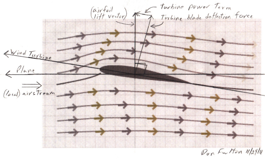
Airplace wing air flow diagram marked up (by me) to
show how it also applies to wind turbine blade.
In a wind turbine the blade rotates directly toward
its front edge since it is held oriented 'flat' to the external wind.
(original airplane wind air flow diagram from PBS
Nova)
Turbine blade view
Here's the same
figure (above) rotated 8.75 degree counterclockwise so blade travel is
(exactly) horizontal. This shows the airflow from the turbine's perspective.
Sitting on the blade the air is seen to be coming in at a small angle (here
8.75 degrees) below the direction of travel. With this view I can
begin to understanding something of how the turbine blades affect the wind
(in a ground frame of reference). See the next section.
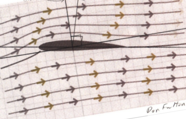
above airfoil figure rotated 8.75 degrees counterclockwise
here (wind turbine) blade motion is horizontal and
(external) wind is vertical
Interpretation
In this figure the
airstream arrows are vector combination of wind (vertical) and blade travel
(horizontal).
Notice the upward component of the airstreams right, after the blade has
passed are lowered, i.e. the wind has been slowed. You can see from the
figure that this slowing exists for both air that has passed over and behind
the blade and air that came near (and reflected off) the blade on the bottom.
However, the slowing is more pronounced for the air 'over the blade', as
its airstream arrows right are almost completely horizontal.
This tells me that air passing both sides of the airfoil are transferring energy to the blade, but the air over the back is contributing more. Air racing up and over the front surface reduces dynamic pressure on the front surface, while air that loosely speaking 'reflects' back off the bottom of the blade increases pressure on the bottom side of the blade, but the negative pressure ('pulling') force is stonger than the positive pressure ('pushing') force along the direction of blade motion. Thus of the two components of air around the blade the 'up and over' component contributes more of the energy the wind turbine captures. Of course, and this may be a key as to why wind turbines are so efficient, the wind reflected backward (a little) by one blade is available to pass up and over the next blade.
Consistent with the viewpoint that the blade 'reflects' some bottom air back, here is figure from a wind turbine simulation showing an effect (velocity or pressure) in front of the blades. (It's from YouTube and not well labelled.)
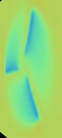
Pressure or velocity (differential) in front of wind
turbine blades
Obvious differences --- variations in speed and angle
of attack
Unlike a plane,
where the whole wing is going at the same speed and same angle of attack,
each section of a turbine blade operates at different wind speeds and different
angles of attack. Near the tip the wind speed is typically x7 higher than
the wind speed and it declines proportionally with the radius: half speed
at half radius, quarter speed at quarter radius, etc. The angle of attack
in a wind turbine blade depends on a vector combination of rotation speed
wind and external wind, so it increases going down the blade as the rotational
wind decreases.
If the outer half of the blade were flat to the wind (it's not, there is some twist), the angle of attack would go from 8 degrees near the tip to about 16 degrees in the middle of the blade, and to still higher angles in the inner half of the blade. Since lift forces peak around 15 degrees and then rolls off and above 15 degrees drag increases substantially, the inner part of the blade is twisted to reduce the angle of attack seen by the blade surface.
A less obvious difference --- high angle of attack
One less obvious
difference between wind turbine blades and airplane wings is that the angle
of attack is higher in wind turbine blades. In most airfoils (at a given
speed) lift force rises (pretty much) linearly with angle of attack, peaking
around 15 degrees and then rolling off as drag increases. Wind turbines
operate in the upper half of the usable 0 to 15 degree angle of attack
range. The wings of (powered) airplanes operate somewhat further down the
angle of attack curve and high performance glider planes operate way down
at very small angles of attack (like 1.5 degree).
So why do wind turbines operate with angles of attack so high? The reason is wind turbines are generating power! High power means high torque on the blades, high torque means high lift, and high lift means high angle of attack.
Another less obvious difference --- force vs work
In the aerodynamic
analyses of airplane wings I have seen it is never pointed out that the
lift force generated by the wing is just a simple force, there is no energy
involved, no work. Work is energy and mathematically [work = force
x distance], but an airplane in level flight is neither rising nor falling,
so all the wing lift force is doing is cancelling the downward force of
gravity. The function of lift on a wind turbine blade is very different.
Blades connected to a generator and power line are difficult to turn, it
takes a lot of force, but they do rotate. In a sense the lift force on
the blade is stonger and overcomes the retarding force from the generator.
Because the lift force on a wind turbine blade is continuously acting through
a distance, the interaction of the air with the blades causes a large amount
of the wind's kinetic energy to be transferred to the blades, which is
of course the purpose of a wind turbine! This work difference (I suspect)
makes the details of the air-blade interaction different in a wind turbine
than in an airplane wing.
Dimensional viewpoint
While looking
at simulations of air flow through wind turbine blades, I realized that
turbine air flow can be looked at dimensionally. The outer part of the
blade is typically going at x7 wind speed. It struck me that 7.0 is pretty
close to 2pi (6.28), so while the blades make one complete rotation, the
incoming air (if unobstructed) would move through a distance of roughly
(90%) the radius of the blade circle. So for a three bladed turbine at
tip speed ratio of 7, the distance the incoming air moves (toward the tower)
between passes of a blade is almost exactly 30% of the radius.
CheckThus the higher pressure 'wind slow down' effect, indicated by the above figure, needs to extend out to about 30% or so of the radius to limit the amount of air that can 'sneak through' the blade circle without coming near a blade.
When the Enercon E82 hits max power (2 Mw) the period is 3.1 sec, or 1.03 sec between blade passes. 30% of its 41 m radius is 12.3 meters, and the curves show it hits full power at winds of 12 m/sec wind. (check)
Lift vector
By definition
the lift vector of an airfoil is perpendicular to the direction of the
incoming air stream, and most of the force generated by the flow of air
by an airfoil (at typical, low angles of attack) is in this lift direction.
To achieve good lift the airfoil is always oriented at a slight
angle (upward) to the incoming air stream. The perpendicular lift force
is due to a combination of air hitting the airfoil on the bottom (its flatter
side), this is the biggest term, and some air flowing more quickly over
the top more rounded surface, which according to Bernoulli's law lowers
the pressure on the top of the airfoil. The 'angle of attack' is pretty
much the same (8 degrees or so) in both airplane wings (in level flight)
and in wind turbines blades (near the tip). In the figure (above) the wind
comes in from the left exactly horizontal and the (plane) wing is
shown slightly tipped, such that the airflow is pointed toward its bottom
surface.
In a plane a baseline 'angle of attack' is built in by attaching the wings to the plane fuselage such that front of the wing it tilted upward. To an observer riding on the front of an airplane wing he sees the air coming in at an angle slightly below the axis of the wing (towards the wing bottom).
Blade 'flat' to the wind
It is important
to understand that in a wind turbine (at midband speeds) the blade out
near the tip is held oriented flat into the external wind. This
means the blade rotates towards its front edge, along the axis of its airfoil,
without a built-in (hardware) angle of attack. For a wind turbine in 10
m/sec wind the (local) air speed near the blade tip will be about 70 m/sec
(154 mph), because tip speed is typically controlled to be x7 wind speed.
Visualize a quick wind drop out
To see how a wind
turbine blade (near its tip) can have a similar angle of attack to an airplane
wing imaging yourself riding on the front of the blade. If the wind suddenly
stops and the blade is still turning, you will feel hurricane force winds
blowing directly in your face in the direction of motion as the
blade cuts through the still air. When the (external) 10 msec wind suddenly
resumes, you will feel the incoming wind shift direction about 8 degrees,
so it now appears to be coming in at an angle of about 8 degrees to the
right of the direction of motion (away from the nacelle, toward the incoming
wind). The reason it's 8 degrees is because [tan^-1 (1/7) = 8.1 degree],
a vector combination of 70 m/sec wind due to the motion of the blade with
the perpendicular 10 m/sec (external) wind.
Difference between airplane wing and wind turbine blade
Riding on
the front of an airplane wing flying at 154 mph you feel the same airflow
as riding on the front of a wind turbine blade (out near the tip) in 10
m/sec wind, a high speed inrushing air stream coming in at angle of about
8 degrees
below the axis of the airfoil. Thus the figure above applies
in both cases with the only difference between the airplane wing and the
wind turbine blade being the direction of the airfoil motion. In
the case of the airplane the airfoil is moving directly into the local
air stream, but in a tipped up orientation (its angle of attack). In the
figure (above) the airplane wing moves left along the line marked 'plane'.
In the case of the wind turbine the blade is held oriented 'flat' to the incoming (external) wind, so rotation of the blades cases the airfoil to advance along the axis of the airfoil. In the figure above the airfoil is moving not directly into the local air stream but at an angle of about 8 degrees from it (providing the angle of attack), leftward along the line marked 'wind turbine'. In the case of the wind turbine blade the angle of attach come from vectorily adding high speed wind from blade rotation to the (external) wind.
Resolve the lift vector along the direction of blade
motion
Now we can
see how using an airplane figure a wind turbine blade works. Here is the
key. In the case of the wind turbine blade the lift force vector (which
is perpendicular to the local air stream), when resolved into vectors perpendicular
to the direction in which the blade can move (line marked 'wind turbine')
there is a component (about 15% of the lift force) pointing in the forward
direction driving the blade forward. This is why a blade/airfoil is driven
toward its rounded front end, even though when observed from the ground
the blades are seen to be mounted flat to the wind. The forward pointing
component of the blade lift force vector is what rotates the blades and
powers the turbine. In the case of the turbine the 8 degree angle of attack
comes from the vector combination of the real (external) wind and the induced
wind due to the high speed rotation of the blades.
Here is another take on it (same explanation, different
words)
Lift is 'defined'
as a force generated by air over and under the airfoil. The orientation
of the lift vector is perpendicular to the incoming air stream,
not to the direction of motion, but to the incoming air stream.
Airplane wing
The airplane in level flight is going forward directly into the air stream (hor above). So for a plane wing with a typical upward angle of attack, lift force vector points straight up and just opposes gravity. It does not driving the plane forward.
Wind turbine----------------------------------------------------------------------------------------------------------
The same airfoil used in a wind turbine can be operated at the same angle of attack, but this is done in a rather curious way. In a wind turbine the airfoil (in the outer part of the blade) is oriented 'flat' to the external wind, so forward blade direction is along the long axis of the airfoil. The high operating speed of the blade tip (x7 wind speed) causes the local wind seen by the turbine airfoil to be dominated by the wind induced by the blade motion, and the angle of attack by a shift in the angle of the local wind from directly toward the front to slightly at the bottom of the air foil by the (vector) addition of the external wind. Thus the angle of attack is controlled by the ratio of the induced rotation wind to the perpendicular external wind (normally controlled to be about x7). A vector combination of a 70 msec headwind with a 10 msec external wind causes the incoming wind seen by the blade/airfoil to be rotated about about 82 degrees from the (external) wind, coming into the airfoil at an angle about 8 degrees below the long axis of the airfoil (8 degree angle of attack). (See the figure above).
Power =
Torque
x angular speed (rad/sec)
= [radius x Force (forward)] x angular speed (rad/sec)
Wind energy declines with radius
Each radius section
of the blade needs to harvest as much as possible of the kinetic energy
from the wind that it 'sees' at its radius. To think about this let's compare
a 1 meter blade section halfway down the blade to a 1 meter section near
the tip. These 1 meter blade sections are slicing through 1 meter thick
radial shells of the incoming airstream. Halfway down, the blade
is only going at half the speed of the tip (in m/sec), so it will cut through
only half as much air, which contains only half as much kinetic energy.
Hence if all blade sections are made equally efficient, a 1 meter section
halfway down can only generate half the power of a 1 meter section near
the tip.
* 1st design rule for the blade (given that available
wind power increases linearly with radius)
Torque (and power) contributions of blade sections should increase linearly
with radius
Constant forward component of lift force
The equations show
that if 'Force' is constant for each section of the blade, then torque
will be proportional to the radius as desired. Halfway down the blade the
torque will be half, because the radius is half. But the power producing
'Force' in the equation above is not the lift force, or even the
the main component of the lift force, which just bends the blades a little
toward the tower, it is the (small) component of the lift force that points
in the direction of the blade motion.
* 2nd design rule for the blade (for all blade sections
to be equally efficient):
Forward component of blade lift force should (ideally) be the same for
all blade sections
Variable wind speed along the blade
It's easy to say
the forward component of lift force should be the same for all blade sections,
but is this achievable? The obvious problem a rotating airfoil has, that
an airplane wing does not have, is that each section of a wind turbine
blade/airfoil sees a different wind speed, a wind speed that increases
as the radius. However, the problem is worse than this, because the lift
equation contains a term showing that lift depends on wind speed (and hence
radius) squared.
Wanted: two compensating 1/r terms
For an efficient
blade we want lift force at each radius section to be the same, but the
variation in wind speed causes the lift (per unit area and for constant
angle of attack) to increase as the radius squared! Hopeless? No.
There are ways to introduce compensating 1/r (multiplying) terms.
One compensating term is provided free by the wind. As the figure below shows, at the slower rotational air speeds seen lower down on the blade the lift vector leans more strongly toward the direction of blade motion. The slower the rotational air speed the more the lean, so the higher the fraction of the lift force that pushes the blade forward. Since for small angles the inverse tan is equal to the angle (in radians), the automatic reorientation of the lift vector direction naturally provides one approximate 1/r term.
Inner blade lift force leans more in the direction
of rotation
The 'lift' force vector (by definition and in practice) points perpendicular
to
the direction of the incoming airstream ('w') as seen by the blade. As
you go down the blade from the tip, the rotational 'wind' term ('u' wind,
see sketches) gets smaller, because the (2 pi r) circumference each piece
of the blade is traversing gets smaller.
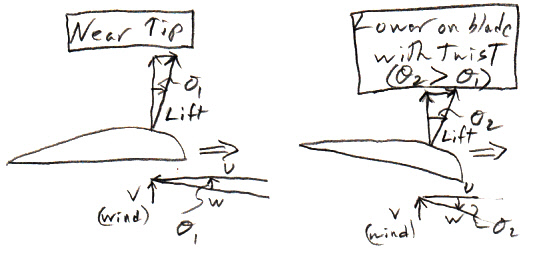
my little sketch showing more forward lean of lift
vector lower on blade
with compensating blade twist to reduce angle of attack
'u' rotational 'wind'
'v' real wind
'w' combined wind seen by blade
If near the tip the rotation 'wind' term ('u') is say 70 m/s (@ 10 m/s wind), then halfway down the blade it will be 35 m/sec. Going down the blade from the tip the decreasing 'wind' vector due the blade motion causes the incoming air stream ('w') to approach the blade at a steeper angle (see sketch), in turn causing the perpendicular lift vector to lean more forward (which is good). Typical values are a lean of 8 degrees near the tip and 16 degrees at the center of the blade. This is a direct result of the usual tip speed ratio being 7 since tan^-1 (1/7) = 8.1 degree.
Note this increase in forward lean of the lift vector for reduced radius is independent of blade twist. It simply falls out of the wind vectors.Two wind terms
* 3rd design rule for the blade:
Blade
geometry lift terms (blade area x angle of attack) should vary
as 1/r.
(Note, this is difficult to achieve near the hub)
As we travel from the tip to the hub the blade geometry must change so that its lift multiplier (not the absolute lift) increases. The lift of a blade radius section is proportional to its width and angle of attack (up to about 15 degrees), thus the product of these terms needs to vary as 1/r. This means doubling halfway down the blade and doubling again at 1/4th the tip radius.
A look at the detailed specification of the 5 Mw NREL wind turbine in appendix and the look of real turbine blades shows how this is done. Traveling down from the tip we see that for half the blade (outer half) a gradually widening with the angle of attack held nearly constant. Halfway down the 5 Mw turbine blade the width has doubled (4 m vs 2 m near the tip), and the (intrinsic wind) angle of attack of 16 degrees has been reduced to 9 degrees, just slightly above the 8 degrees near the tip, by a 7 degree blade twist. Traveling below the center of the blade width continues to increase, most turbine blades show a noticeable bulge in width around 1/4th radius (bulge is very modest in the NREL 5 Mw spec), and twist allows the angle of attack to increase from 8 to 15-20 degrees, which provides another factor of two.
* 4th design rule for the blade:
In the outer half of the blade increase lift primarily by widening the
blade using twist to hold the angle of attack nominally constant (8 degrees
for tip ratio of 7). In the inner half of the blade increase lift by both
widening the blade and increasing angle of attack (up to max of 15-20 degrees).
It's not possible to keep the blade geometry lift terms growing as 1/r as the radius gets small, but there is relatively little wind kinetic energy in this radial region. Looking at the area of the blade circle we see the fraction of wind energy inside 1/4th of the blade radius is only 6% and inside 1/8th only 1.5%.
But note loss of a few percent of energy down near the hub (due to the blades at slow airspeeds being inefficient) makes the overall 50% effiency of wind turbines all that more remarkable. 50% efficiency obtained using only 95% of the blade circle makes the efficiency of the working area of the turbine 52.6%.
A less obvious blade/airfoil criteria
There is another
criteria for wind turbine blades, well known to aerodynamic engineers,
but less obvious. This has to do with the blade surface roughness/smoothness
and maintaining it over time. The surface characteristics of airfoils are
important as they affect the air flow. In a wind turbine over time the
blade can get dirty or buggy, especially the leading edge where airflow
is near zero. (Solar panels have the same problem with dust.) The National
Wind Association says blades developed over the last 20 years are much
less sensitive to "blade fouling caused by dirt and bug accumulation on
the leading edge". Oh yes, engineer's tricks.
-------------------------------
Blade
numbers from 1999 Bonus Turbine paper
The 1999 Bonus
turbine paper gives the following numbers. Says the vector sketch is not
to scale. The rotating vectors are about x20 bigger than shown. This is
an old turbine where the blade speed was fixed by use of an induction generator.
The turbine is the (Danish) Bonus 450 kw Mark III operating in 10 m/sec
wind. Scaling using blade dia from other turbines it may be putting
out 300 kw at 10/msec, but it could be less as its speed may not be optimum.
Numbers don't quite add up, suspect they were rounded off in article: If
35 rmp quoted as 30 rpm, it gives right 2 sec period and 50 m/sec (within
10%).
Turbine power
450 kw peak, 300 kw @ 10 m/sec (est)
Rotor dia
35 m
Wind speed
10 m/sec
Tip rotation speed
50 m/sec (tip speed ratio = 5)
Incidence angle
11.3 degrees (tan^-1 1/5)
Rotation rate
30 rpm (2 sec period) spec is 35 rpm
Blade wind pressure
static blade
80 newtons/m^2 @ 10 m/sec
Basically Bernulli dynamic pressure (0.5 x density x vel^2)
times a lift coefficient
(1/2) x 1.275 kg/m^2 x 10^2 x 1.25 = 80 N/m^2
rotating blade
1,500 newtons/m^2 @ 51 m/sec (lift force almost
perpendicular to incident wind)
(1/2) x 1.275 kg/m^2 x 51^2 x .90 = 1,500 N/m^2
Forward pressure
300 newtons/m^2 (= 0.2 x 1,500)
forward component of lift torque generating power
Power/blade
100 kw (60 kw for outer 1/3rd of blade with
av radius 0.83 x 35/2 = 14.6 m)
Power = T x w = F x radius x w
F = Power/(radius x w)
= 60,000 watt /(.833 (35/2) m x 3.14 rad/sec)
= 1,300 newtons = (5.8 m x 1.5 m (guess) x 150 newtons/m^2
ballpark (at 83% out on blade) pressure will be higher and closer to
300 newtons/m^2 at tip
Lift formula
Formula for lift is just the formula for Bernoulli 'dynamic pressure' [(1/2)
x (air density) x vel^2] times the lift coefficient.
Lift force = [lift coefficient] (1/2) x air density x v^2 x area
typical lift coefficient range is 0.5 (0 degrees) to 1.75 (15 degrees)
(0 degree angle attach lift force of 0.5 is due to assymmetrical airfoil
with a longer path over the top)
v = (incoming) airstream velocity
check
Lift/area = [lift coefficient] (1/2) 1.275kg/m^2 x (51 m/sec)^2
= [.90] x 1,660 newtons/m^2
= 1,500 newtons/m^2
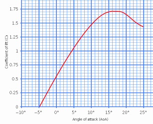
Lift coefficient vs 'angle of attack' for typical
airfoil
Lift force of most airfoils peaks around 15 degrees
and then rolls off
(peak is called 'critical angle of attack', above
peak is the stall region)
(source -- http://en.wikipedia.org/wiki/Angle_of_attack)
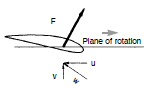
Twist on inner blade (reduced 'u') tips front of blade
into wind ('v') to reduce angle of attack
http://www.windmission.dk/workshop/BonusTurbine.pdf
-- The angle of attack (for an airplane wing) can be simply described as the difference between where a wing is pointing and where it is going.
-- While the common meaning of the word "lift" assumes that lift opposes gravity, lift in its technical sense can be in any direction since it is defined with respect to the direction of flow rather than to the direction of gravity.
-- Rear side of the blade is more curved than the front side
-- If the wind imparts a torque on the blades then the blades must be imparting a torque on the wind. This torque would then cause the exit air flow to rotate. Thus the flow in the wake has two components, axial and tangential. This tangential flow is referred to as wake rotation.
-- Newtonian mechanics defines power as torque multiplied by the rotational speed. The same amount of power can be extracted by allowing the rotor to rotate faster and produce less torque. It is common for the tips to be moving through the air at 7 times the speed of the free stream. Less torque means that there is less wake rotation. Less wake rotation means there is more energy available to extract. This wake rotational loss is minimized by allowing the rotor to rotate very quickly.
-- Betz was able to show that the maximum coefficient of power of a wind turbine is 16/27 = .59. Airflow operating at higher thrust will cause the axial induction factor to rise above the optimum value. Higher thrust cause more air to be deflected away from the turbine. When the axial induction factor falls below the optimum value the wind turbine is not extracting all the energy it can. This reduces pressure around the turbine and allows more air to pass through the turbine, but not enough to account for lack of energy being extracted.
-- In
the Betz turbine the energy extraction manifests itself through thrust.
The equivalent turbine described by Betz would be a horizontal propeller
type operating with infinite blades at infinite tip speed ratios and no
losses.
-------------------------------
Pressure of an airfoil
References say the pressure of an airplane wing (positive below, negative
above) is appox the (Bernulli) dynamic pressure. (The lift coefficient
is in the formula, but to a first order it is about 1.) Average speed is
some fraction of tip speed, not sure what faction to use, but I will guess
at .666 the radius.)
Dynamic pressure = (1/2) density x vel^2
= (1/2) x 1.275 kg/m^3 x [ .666 x (2 pi x 46.5 m)/3 sec]^2
= 2,400 N/m^2
Note with these guessimate numbers we find the average pressure across the blade circle area to be about 1.5% of the average pressure created by a single blade (35/2,400 = 1.46%). Thus one way to view how a wind turbine works is that the large pressure ridges from the three blades that sweep around the blade circle are somehow smoothed out over a second or so time interval (by air density changes?) to provide the average pressure drop across the whole blade circle needed to extract 50% of the kinetic energy from the wind passing through the blade circle.
The problem with this picture, as was pointed out to me by an expert and can be seen in wing pressure diagrams, is that the dominant wing pressure (especially at lower angles of attack) is negative pressure above the wing. In a wind turbine this negative pressure is downstream, so how does high negative pressure behind the blade work to pull the kinetic energy from the incoming wind? I can see from wing flow diagrams that if the blade comes through slicing leftward, then the air flowing behind the blade is thrown rightward (making Newton happy), and it must exit with reduced kinetic energy having done work on the blade, and much of this kinetic energy is probably directed circumferencely. If this is right, then the picture is in the wake of the moving blade the air downstream has only a weak downstream motion. Hence it forms sort of a barrier and pushes back on the incoming wind upstream slowing it and raising its pressure.
How all this upstream increased pressure air transfers almost half its kinetic energy to the occasional blade passing through I have yet to see anyone explain.
------------------------------------------
Bernoulli effect
The hyper-physics
site says the way to think about the Bernoulli effect (moving fluids have
reduced pressure) is to consider pressure to be the energy density
of a fluid.
Energy = Force x distance
= Pressure x Area x distance
= Pressure x volume
hence
Pressure = Energy/volume
When fluid is forced to flow, say over the top of an airfoil cutting through it, the flowing fluid clearly has acquired a kinetic energy (0.5 x density x vel^2). Where does this kinetic energy come from? By conservation of energy it comes from a reduction in the (static) pressure of the fluid. Hence fluid (static) pressure is reduced by its dynamic pressure.
dynamic pressure = (1/2) x density x vel^2
where
dynamic pressure in kg/m^2 (pascals)
density in kg/m^3
vel in m/sec
Narrow blades
This photo
of a large turbine (Enercon E-126 at 7 Mw the world's biggest turbine)
shows clearly how narrow the outer third of the blade is, and the outer
third of the blade provide about 56% of the wind turbine power.
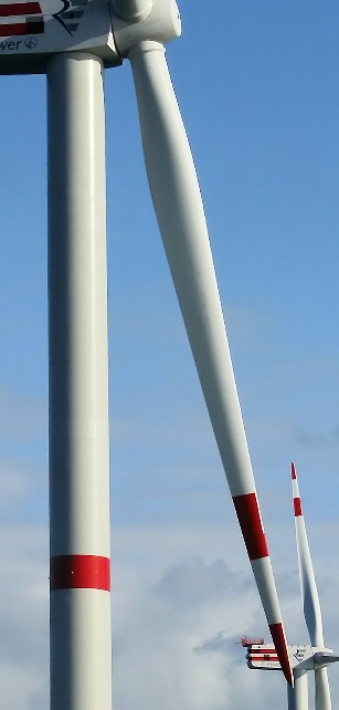 .
. 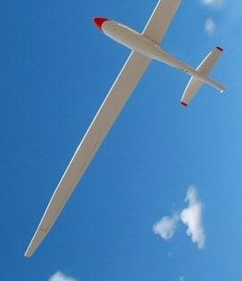
(left) 5 Mw turbine (blades shown feathered)
Notice thinness of outer section
(right) glider plane wing
(source -- http://en.wikipedia.org/wiki/Wind_turbine#Horizontal_axis)
Wind turbine start
Turbines have
a very weak starting torque. For this reason the generator imposes no load
on the blades until they reach 25% or so of their top speed. If the generator
was to be switched on all the time, a wind turbine would (likely) never
start. There is a positive feedback effect at start that can be seen more
easily with small fast rotating turbines. Blade rotation is very slow at
first and then it sort of takes off. Big turbines do this too, but it's
harder to see. The acceleration occurs because the lift force has a velocity
squared term in it, so the faster the turbine goes, the more the torque
it generates, and without a significant load this torque provides increasing
acceleration of the blades.
But there is an interesting question about wind turbine start. Why do they start? Consider, much of the blade is flat (or almost flat) to the wind. When a head-on wind hits a flat surface, there is no torque. So why does a turbine start? Is it powered? A powered start (in principle) is possible using the line or batteries to run the generator as a motor, but as far as I know no commercial horizontal wind turbines use a powered start, they all start using only the force of the wind. (However, Wikipedia does say that one type of vertical wind turbine, Darrieus turbine, often will not start without a 'kick'.) Most of the torque (I think) comes from the large flared section of the blade near the hub that has a substantial twist. The twist is the key.
The twist is such that the leading edge of the blade points outward (toward wind). This twist does two jobs. In normal operation it reduces the (too high) angle of attack of the wind near the hub, keeping drag down and forward torque up. But it has a second job, which is helping the turbine start. A canted blade by deflecting wind tangentially provides torque even when stationary. Blow into an unpowered room fan, and it moves in the direction of the forward side of the blade. Same mechanism is at work in a turbine at start. The air hitting the twisted section of the blade is deflected with a tangential component causing an equal and opposite reaction on the blade pushing it in the forward direction.
Video of turbine start
Slow.... 7
min video of a wind turbine starting. At first no rotation with blades
pitched 90 degrees. Around 2 min the blades rotate into the flat position.
and very slowly it starts to turn. The text says at 5 1/2 min full speed
is reached. The twist of the blade can be seen.
http://www.youtube.com/watch?v=LtGH5FzyaII
=====================================================================
There are lots of other ways to built a wind turbine designs besides the standard wind turbine described in this essay. There are probably dozens, new one continue to be invented, lots of little companies are working on them, the Wikipedia article 'wind turbines' describes lots of them. I've looked very little at alternate designs because the three blade, hor, into the wind is the universal standard. As far as I know, every large turbine built or (seriously) planned is this design, but a couple of the far out alternates have caught my eye.
Here from Wipeidia (Wind Turbine) is a nice gif image showing the three basic types of wind turbines.
left: drag vertical
turbine
middle: lift horizontal turbine
right: lift vertical turbine
Vertical wind
turbines
Vertical wind
turbines rotate around a vertical axis. Nearly all of them are fairly low
power. With the huge interest in wind turbines for the home and rural market
new one are being invented all the time. There's now an amazing number
of them. The are simple compared to large wind turbines, being radially
symmetric they don't care about wind direction, and the generator is mounted
low. Here is just a partial sample from a Google image search 'vertical
wind turbines'.
Yikes --- partial results of Google image search for
'vertical wind turbines'
Savonius
(vertical, drag) wind turbine
Some have
blades shaped into scoops. It's clear from looking at them why these wind
turbines rotate. These blades are obviously designed to catch the wind
and are rounded on the back to let the air flow around them. The aerodynamistists
call this a wind turbine that works on the principle of drag.
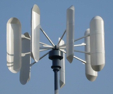
drag vertical wind turbine
Darrieus
(vertical, lift) wind turbines
There's a
type of wind turbine with narrow, vertical, flat to the wind blades where
it's less than obvious why it rotates. In fact, if you had asked me not
long ago why it rotates I would not have had a clue. It seems amazing that
an array of nearly flat, vertical blades want to rotate so robustly. That
is, once it gets going, because as Wikipedia notes this (basic) design
is not normally self-starting.
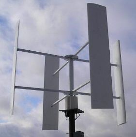
Why does this rotate?
Giromill vertical wind turbine with straight (airfoil)
blades
Why it rotates
The explanation
for how this type of wind turbine works is simple, if the basic principle
is remembered that an airfoil moving fast and perpendicular to the
wind is driven forward by a component of the airfoil lift. Look at the
front blade in the picture. As it sweeps by horizontally, it is moving
just like the (outer part) of blades of large turbines as they over the
top and bottom of their circle. The back blade basically works the same
way except it's airflow is not as clean due to blades passing in front.
The side blades are not going to make any torque as they are not moving
perpendicular to the air flow. The result is that four airfoils (like in
the image above) rotating horizontally will produce less than half
the force they would if they were rotating vertically, because with vertical
rotation each airfoil works effectively at all angles.
Makani Flying
Wing turbine
I semi-screwball
idea that I would bet 100 to 1 will never develop commercially is to make
tethered flying wing kites into turbines. Makani
Power has some small prototypes flying. Why do I say this? Consider
the size of the blades that need to be mounted on the wing to brake it.
Can you envision a flying kite with blades the size you see in current
medium to large turbines? The mind boggles. These are kites, supposedly
programmed to fly in circles, but think of how far apart they would need
to be to avoid tangling. What about if one of these things came down with
blades spinning? Advocates show them over the ocean. Probably this is the
only place they could be used from a safety viewpoint.
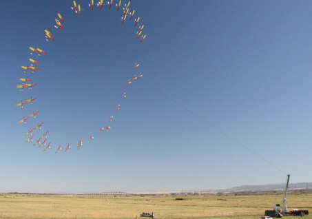
tethered Makani flying wing prototype flying in circle
source -- http://www.makanipower.com/
Makani's marketing
hype is that the outer blade of a wind turbine is the most efficient part
of the turbine (sort of true), so a tethered wing flying in circles braked
by propeller driven generators mounted on the wing is the way to go. Can
you say reliability nightmare and high operational cost? On the other
hand it does look cheap to build, would have the advantage of good air
higher up, and they have a neat video show how by powering the propellers
they can launch and retrieve it vertically like a helicopter. The largest
plans they have drawn up is for a (small) 1 Mw unit, which looks like a
small plane and has six propellers. About a dozen engineers, several from
MIT. I was surprised to find Wikipedia has a 'Airborne wind turbine'
page, which says (surprise), "As of 2011, no commercial airborne wind turbines
are in regular operation."
=================================================================================
Astralux Ltd (Ukraine) wind turbine scam --- DBK equivalent
in wind turbines
(update 3/23/13)
Astralux wind
turbine has morphed in the last couple of years, becoming even more like
DBK. Like dozens of other backyard inventors they have now built themselves
some hardware: a vertical wind turbine prototype of their design they rate
at 2 kw. So far so good, but there is a scamy side to Astralux too. The
strong claims made for the hardware are unsupported by data, and the claimed
features of its design are in many ways absurd. Overlay this with grandiose
and totally unrealistic plans to scale up the technology, and here is the
real red flag, trolling for naive customers on a related site with promises
of delivery for hardware they don't have (and almost for sure never will
have) with the requirement that customers pay 50% up front on all
pre-orders.
Here's the flavor of their claims, from their home page:
"We are ready to service orders for wind turbines up to 10 kW of power." Really? A x5 scale up is a stretch for company that apparently has only built a single 2 kw prototype, but perhaps not totally absurd, but the very next sentence we get this:Scam flags"In the future we will build a wind turbine plant that produces up to 1 GW of power that will soon become the basis of the wind power industry." Now we really move into the realm of the absurd, into fantasy land. While slightly hedged with "up to" for a 2-3 person company to state "we will build" a wind turbine that is x500,000 larger than they have every built and more than x100 times larger than any wind company on earth has every built is ridiculous.
* They claim as an advantage that while rated power is obtained at 10 m/sec wind (consistent with most turbines) as wind speed increases their output power continues to increase. They say x4 rated power at 15 m/sec wind and the turbine can be used to 40 m/sec wind. Since power in wind goes as the cube of speed, at 40 m/sec wind the turbine output power is potentially 4^3 = x64 times higher than rated power, and in fact we find graphs of the turbine's output power vs wind speed showing just this!!
Operating over a wide overspeed wind speed range (10 to 40 m/sec) poses an impossible engineering challenge in two ways. First, the conversion electronics cannot be economically designed to handle huge transient surges when the wind blow fast. Second, the actual windings in the generator can't handle huge overloads either. An wind speed increase from 10 m/sec (rated speed) to 40 m/sec presumably means the turbine would potentially rotate x4 faster, and with a PM generator this means x4 higher voltage. However they claim output power continues to increase in the overspeed range reaching x64 higher (!) at 40 m/sec. This is, of course, theoretically possible since power goes as wind speed cubed, but from an engineering point of view it is a nightmare. With voltage up x4, current must be up x16 to give x64 power, but there is a pesky little problem here with ohms law. A x16 increase in current means (ohmic) heating in the winding increases by 16 squared or x256! Can you say idiots or fraud?
* The Astralux site is dominated not by reasonable size turbines they could conceivably build, but by fantasy polished artworks showing monster versions of their wind turbine design on the landscape and mounted on top of skyscrapers.
Prepayment red flag
The
scam red flags really go up when on another site I find a release from
Astralux that includes this:
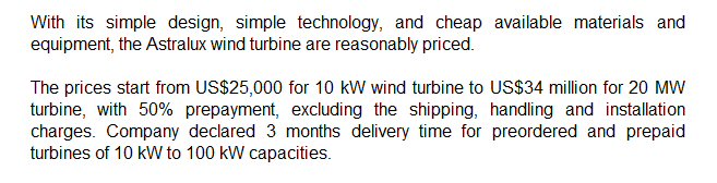
Note the text: "with 50% prepayment" !
Delivery: 100 kw in three months, when they have only
built a 2 kw prototype!
screen capture 3/23/2013
source --- http://pptymag.com/10mw-wind-turbine-quadruples-power/4730/
They are pricing a 20 Mw unit for 34 million dollars (US) with (get this) "with 50% prepayment". This is from a 'company' that business sites say is 1-10 people whose only hardware is apparently a single 2 kw prototype. A 20 Mw unit would be a scale up of the prototype of x10,000!! I know as an engineer this is not how engineering works, scaling up by x10 can be very difficult, and scaling by x10,000 is a joke. A release like above screams scam.
Astralux is saying advance us 17 million and we will deliver a 20 Mw wind turbine. Note a 20 Mw turbine is about x3 larger than the biggest turbine ever made by huge companies like GE and Siemens! Oh yea, your going to get a turbine if you upfront 17 million, and they have a bridge in Brooklyn you might want to bid on too. Another April fools joke or tolling for suckers? You decide. The 20 Mw turbine even has a "planned release date - end of 2015".
I note also on their main site one of the Astralux contacts handles "orders".
Delivery red flag
And to take
the fraud to another level above promises "3 months delivery time" for
turbines up to 100 kw, which is x50 larger than they have ever built. Oh,
yea!
--------------------------------------------------------------------------------------------------------
(update 2/1/12)
Astralux now
has hardware! A crudely built prototype of a 2 kw vertical turbine! There
is a video of it and 'specs'. Here is the announcement (2 kw video
--- http://newwindturbine.com/news/first-commercial-2-kw-wind-turbine-is-developed/)
"First commercial 2 Kw wind turbine is developed"The video is all flash with no detail. The magnetic levitation (if it exists) is not shown in any detail. The video includes no performance data. Rotation is shown from inside the rotor, and the generator appears to be a plethora of vertically mounted magnets (or bars) sliding by vertically mounted coils on the mount.
"We are glad to announce the completion of development of the vertical axis solar and wind power generator on magnetic levitation and manufacture of first commercial sample. "
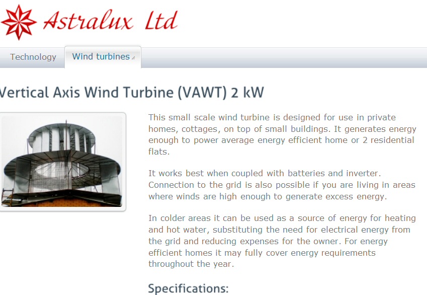
screen capture 2/1/12
(source -- http://newwindturbine.com/wind-turbines/vertical-axis-wind-turbine-vawt-2-kw/)
Nonsense power curves
The nonsense starts
in the accompanying power curves (below) for this 2 kw turbine. The plot
shows 2 kw at 10 m/sec (so far so good), but the curve keeps going to 40
m/sec showing 128 kw (approx) output power at 40 m/sec (88 mph) wind! An
increase of x64 power as the wind increases from 10 m/sec to 40 m/sec means
the torques on the rotor and mechanics goes up by x64, and the output electrical
current (assuming voltage is limited) by x64. And let's not forget the
heating in the generator wire, which from ohms law will go as i ^2, increases
by a stunning x4,096. Talk about an engineering challenge! And all this
overdesign to capture the energy of winds between 22 and 88 mph. Total
nonsense.
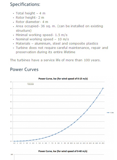
This plot has the 2 kw turbine outputting 8 kw at
15 m/sec!
Material includes no PM magnets, so how does the magnetic
levitation work?
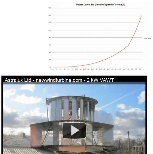
This 2nd plot extends the range to 40 m/sec (88 mph),
where the power is now in excess of 100 kw from a '2 kw turbine'!
(kink in the curve is due to a change in the hor scale)
This is a sloppily drawn cubic curve.
(source -- http://newwindturbine.com/wind-turbines/vertical-axis-wind-turbine-vawt-2-kw/)
Calling interested investorsYup, they are ready to build plants not only in Europe, but also USA! They state they are ready to take orders for turbines up to 10 kw (whether they will ever deliver is another question).
"Astralux Ltd is looking for a qualified investor to finance a construction of manufacturing plants in Europe and USA."
-----------------------------------------------------------------------
A Ukranian
company Astralux
Ltd makes some extravagant claims. They make (so they say) a
tiny little 10 kw turbine, but show specs for vertical wind turbines up
to 20 Mw! And talk of scaling up from there to 1 Ghz! One of their big
claims is absurd.
"Unlike traditional turbines (our Astralux vertical turbine) continues to generate more and more energy till wind speed reaches 40 m/s! For example, 10 MW turbine will generate incredible 40 MW at wind speed of 15 m/s." (Astralux web site)Ignoring the fact that winds of @ 40 m/sec (88 mph) are hurricane force winds and occur so infrequently they would contribute virtually nothing to the average power out, the claim is absurd because of the demand on the electronics and the whole system. Even if the mechanics could handle huge peak overloads (doubtful as it means huge peak torques), how is the power to get to the power line? Are 10 Mw electronics to be designed to handle x4 overload (40 Mw) @ 15/m/sec {or at the extreme x76 overload [758 Mw = (40/15)^3 x 40 Mw] @ 40 m/sec!} to handle an occasion wind surge? I can tell you as a power designer, this is plain stupid. The reason blades are feathered in standard wind turbines above 12.5 m/sec is to protect the mechanics and electronics from power overloads. At the typical maximum working speed of standard wind turbines of 25 m/sec the blade feathering allows 7/8th of the wind's energy to pass through the blade circle unhindered.
Another Astralux dubious claim is that their large rotating drum would be magnetically levitated. With super low friction they claim a very low cut in speed. The problem here would be cost and/or the power required to do the levitation. Magnetic levitation (by opposed PM) is occasionally used for small (<10 Kw) vertical turbines (YouTube video of one being installed on barn roof shows the underside magnets.) The only large structures I have ever heard of being levitated are a couple of prototype high speed trains, where high cost can be tolerated.
Scam? Yup!
I could almost believe
the Astralux web site (http://newwindturbine.com)
is a scam (or maybe a joke). No real engineering, absurd pompous claims
(energy increases up to winds of 88 mph), looking for an investor to build
factories, all contacts in Ukraine, off the wall side claims (wind powered
car). In fact, the more I look at their site the more I smell DBK Solar,
a solar scam I have long tracked. Poking around on their site I found this.
"First in the world wind-powered car". No data, no technology, just two
pictures (see below). Note the car picture caption. If this doesn't scream
fraud, I don't know what does. This is DBK Solar all over again.
On aux sites I found they want 50% advance to pre-order, and Mw size turbines can be pre-ordered for millions of dollars. This wind energy company is 'hands down' a fraud and out to take the unwary.

Astralux Ltd (Ukraine) home page
screen capture 12/7/2011
source -- http://newwindturbine.com/
Not only does Astralux do wind turbines, but they have a prototype of a 'wind powered car'. And by the end of the year you can pre-order one of these beauties!
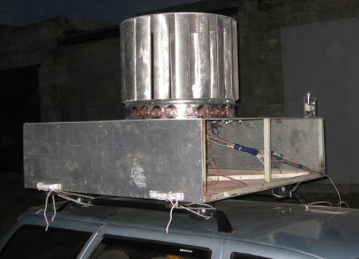
"First in the world Wind powered car"
screen capture 12/7/2011
source -- http://newwindturbine.com/news/car/

caption --- "Cars will be available for pre-order
at the end of 2011" (Oh,yea!)
screen capture 12/7/2011
source -- http://newwindturbine.com/news/car/
(Update 2/1/12) --- Wind powered car is labeled "a
joke"
I checked
back after the pre-order date to see if this had changed and of course
it had (pre-order date is moved out to 2017). On the site searching around
in a forum I find they now label the wind powered car as "a joke". It's
announced date is (was?) shown as April 1, 2010. Did I miss this April
Fool's joke (maybe), or did they just add this date? Don't know. Anyway,
whether it was always a joke, or whether they have recently taken steps
to distance themselves from a ridiculous claim, the wind powered car can
now be dismissed.
LinkedIn says company as 1-10 employees, but you can order 100 kw turbines.
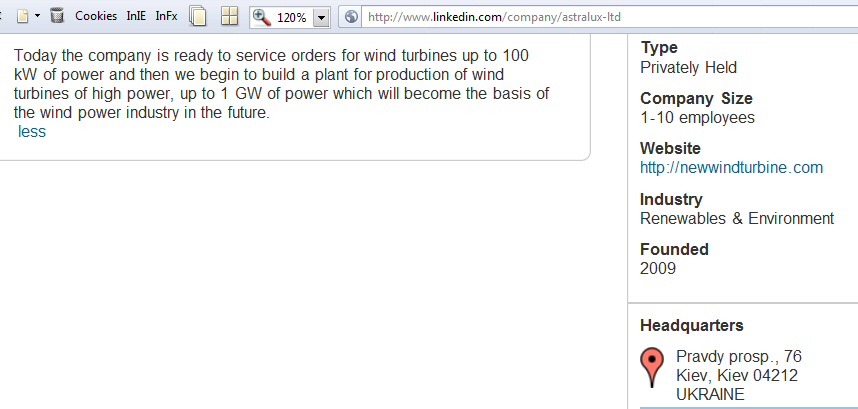
screen capture 12/15/11
Astalux Ltd has other URL's
Astralux Ltd
has another site in english --- http://windturbine.com.ua.
This site has a "photo gallery" showing their huge wind turbines sited
in Nevada and Scotland. They fail to mention the artist has simply drawn
in the turbines.
They are taking orders for the 1 Mw unit shown in the Nevada 'photo'.
"This wind turbine (Nevada picture) is completely ready for installation in wind sites and parks in areas with high and average wind speed. Nominal power of 1 MW wind turbine is already reached at a speed of the wind flow 9.5 meters per second." (http://windturbine.com.ua)
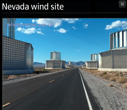 .
. 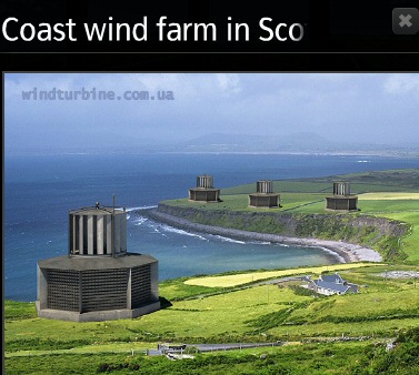
The claims for Scottish baby (right) are off the wall. The site text says it is a "10 Mw Rated" turbine (@ 9.5 m/sec or 7.2 m/sec, both are shown), but at 15 m/sec wind it output 88 Mw! Yup, 88 Mw from a 10 Mw rated turbine. An industry first!
As a retired power engineer who knows something about wind turbines, the claims of this company are absurd. This company is fraudulent. Taking orders for non-existent turbines with money up front is a scam. They are trolling for victims.
Russian link --- http://www.windturbine.com.ua/
========================================================================
I made a real find, a detailed specification for a large wind turbine with everything: dimensions, weights, blade twist, performance numbers. It's from the NREL (National Renewable Energy Laboratory part of Dept of Energy) published in 2009 (link below first chart). It's for a 5 Mw offshore turbine with a calculated power coefficient of .48 at 5 Mw, tip speed ratio of 7.55, blade pitch of 0 degrees.
Angle of attack
There is enough information
in the spec to calculate the angle of attack (and to confirm my explanation
(above) of blade geometry). At rated 5 Mw tip speed is 80 m/sec and wind
speed is 11.4 m/sec, so tip speed ratio is 80/11.4 = 7.0. Aerotwist shows
the tip of the blade is nearly flat to the wind (< 0.5 degree), so near
the tip the angle of attack is tan^-1 (11.4/80) = tan^-1 (1/7) = 8.1 degrees
- 0.25 degree (@ node 16.5) = 7.9 degree
At 3/4 radius, if no twist, angle of attack would be tan^-1 (11.4/60) = 10.8. Aerotwist shows (@ node 3/4 x 17) shows 2.5 degrees, airfoil angle of attack is 10.8 - 2.5 = 8.3 degrees, basically the same as near the tip.
At 1/2 radius the rotational speed is halved, so if there was no twist the angle of attack would be about doubled tan^-1 (11.4/40) = 15.9. But there is a blade twist of 7.1 degrees (@ node 17/2), so angle of attack seen by the airfoil is 15.9 - 7.1 = 8.8 degrees. Again nearly the same as near the tip.
At 1/4 radius, if no twist, angle of attack would be tan^-1 (11.4/20) = 29.7. Aerotwist shows (@ node 17/4) shows 12.8 degrees, hence airfoil angle of attack is 29.7 - 12.8 = 16.9 degrees. Force for most airfoils peaks about at about 15 degrees and then rolls off somewhat, so at 16.9 degrees we are a little over the hump, but still with lift force per unit area of the blade area close to double the outer half of the blade.
The twist does go above 13.3 degrees. At 1/7th radius the rotational speed and wind speed are the same so this part of the blade has an angle of attack producing only modest lift force (45 - 13 = 32 degrees) and a lot of drag. The inner 1/7th of the blade contributes virtually nothing to turbine power, on the other hand only 2% of the wind kinetic energy exists within this radius. In general in the inner quarter of the blade, where 6.25% of the wind energy is, the lift produced is a probably a lot less than ideally required because the area cannot be increased enough and the angle of attack gets too high. Conclusion: the outer 75% of the blade probably produces 98% or more of the turbine power.
Here are some tables from the NREL turbine spec.
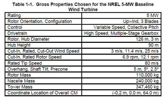
source -- https://ceprofs.civil.tamu.edu/jzhang/ocen407/5MW%20Reference%20Turbine.pdf
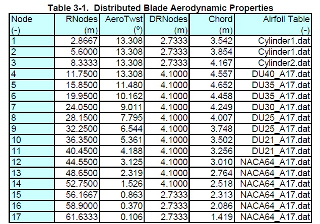
Aerotwist is blade twist
(left) 17 sections of radius (starting at hub)
Chord is blade front-back length
(This wind turbine blade has only a very modest bulge
in its width down near the hub)
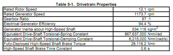
To understand how wind turbines really work, to understand how the incoming air stream is slowed and transfers so much energy to the blades, a good starting point might be to look at wind turbine airflow patterns. I did many Google search and come up with nothing, but finally found a couple of YouTube videos of wind turbine simulations, which as is typical don't tell us what is being done. For example, what is being plotted and what's the color code. A visit to the home site (XFlowCFD) yielded nothing. They have lots of simulations there, which they put up as advertising for their tool.
Unfortunately no key, and no color code info, but looking at these figures some things can be figured out. I already understand from looking at airflow patterns over airplane wings that air must be deflected in the opposite direction of the blade motion. In the 1st figure the turbine is stationary and the wind has just been started. In the 2nd figure a second or so later the blade is just beginning to turn (counterclockwise), and we see a red trail behind the blades, but (more revealing) a green trail behind the tower. In the 3rd pair of figures the turbine is presumably up to speed (good assumption is a tip speed ratio of 7). After capturing the left image I frame stepped for 90 degrees or so blade rotation for the second image. Comparing the detail on the contrails on the right side of both images no rotation is seen. This is crystal clear when frame stepping through the simulation. The contrails thrown off by the blades do not rotate. The blades create this cockscrew pattern which glides backwards (not rotating), presumably carried by the slowed wind, initially intact and then slowly disintegrating.
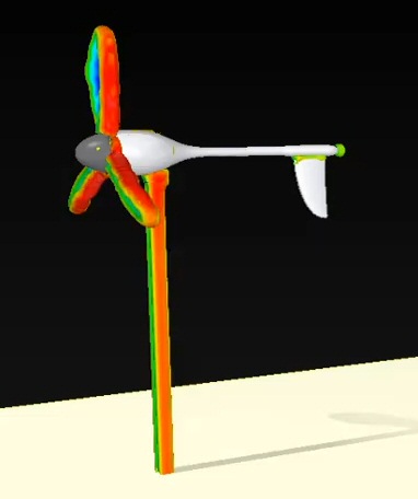 .
.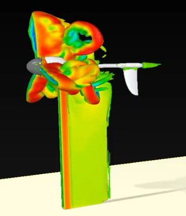
(left) three blade turbine (not rotating) at wind
start
(right) blades just start to rotate counterclockwise
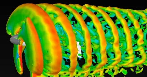 .
.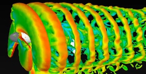
Two images a fraction of a rotation apart
(left first, right with blades about 90 degrees counterclockwise
later)
Note detail in the trailing wind on the right sides
show no sign of rotation
The video was uploaded by XFlowCFD. It is one of many
simulations on their site done using their software.
http://www.youtube.com/watch?v=nj_iL8PXOD8&feature=related
(local) wind_turbine_simulation_xflowcfd.mp4
Color coding
I don't know
how standardized color codes are, but another simulation (below of water
flowing), from another piece of software has a color sequence with increasing
speed: blue, light blue, green, yellow, orange, red. This, of course, is
prism
spectrum with blue used for low amplitude and red high amplitude. I see
this type of color coding in quite a few simulations, and it was probably
used in the above wind turbine images too.
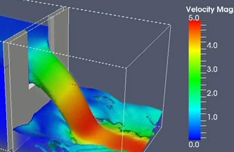
Interpretation --- change in velocity?
I think the
simulation above is showing an air velocity term. It can't be the absolute
air speed (relative to the tower), because nothing in front of the blades
shows, but this is understandable as otherwise the whole image would be
clouded by moving wind. I suspect what is being shown is air velocity minus
the
wind velocity, in other words the change in the wind flow (vectorily).
Each blade has leaves a uniform green contrail with the blade tip throwing out faster moving air (yellow to orange) probably with an outward radial component.
What I see happening is this. Airplane wing simulations show the air over the top of the wind, here over the downstream side of the (say leftward moving blade) is through right a fixed amount, roughly the width of the blade. I say fixed because there is no hint of rotation in the wind turbine contrails. It looks the air makes a quasi-step change in tangential position as blade pass (whipped over the longer back surface), and then just drift backward from the blades with the (reduced) downwind wind speed. In other words after the momentum transfer to the blade (step displacement tangentially) the air has not acquired any real tangential (rotating) velocity or kinetic energy. All the kinetic energy in the downstream wind is contained in flow of the direction of the incoming wind, but presumably flowing a little slower.
Estimating downstream wind speed
There is even
a way to estimate the downstream air speed, but here I run into a problem.
My working assumption is that the tip speed ratio is about 7. 7 is
pretty close to 2pi (6.28). This means that when when a blade has done
one rotation, count back three contrails, since there are three blades,
and the incoming air should have moved a radius. However, downstream
from the blades, where we know the air has lost half it's kinetic energy,
it should be going only 70% as fast. In other words the spacing in the
figure between three contrails should be about 70% of the radius. Unfortunately
it looks to me to be on the order of the radius. (Who knows what they assumed
in the simulation. If they set the tip speed ratio at 10, then everything
checks.)
Here's the same air flow pattern done (by another source) for the 5 Mw NREL turbine (shown in appendix). I know this turbine is designed with a tip speed ratio of 7. Here the spacing between three contrails does look like it is (or could be) about 70% of the radius. Things are looking up.
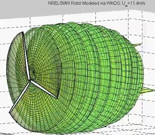
Momentum transfer viewpoint
Consider:The analogy of the motor seem good, the fast moving blade being like the fast moving rotor. The relative force between blade and air, created by the lowered pressure as air flows behind the blade, is analogous to the current pushing against a magnet in a motor. Nearly all the energy transfer by the relative force of the interaction goes into the fast moving blade. The tangential air 'step' displacement (the width of the blade), as it flows quickly over the back surface of the blade, is effectively a kickback to the air.
If a radioactive nucleus throws out a particle (electron or alpha particle) that weights say 1% if the nucleus, then since kinetic energy goes as velocity square, about 99% of the energy of the explosion ends up as kinetic energy of the light particle. The remaining 1% of the energy causes the heavy nucleus to kickback a little. When two mass interact and initially neither is moving, an explosion transfer nearly all its energy to the light component.Assume the rotor of an electric motor is turning fast (like the blade) and current is put into the coils (attached to the case of the motor). This causes a relative torque (think force) between the rotor and the case of the motor, but the energy transfer (from the electrical source) is nearly all to the moving rotor. The case if held rigid will not move and absorb no kinetic energy, if free to move a little it will kickback absorbing a little energy. When initially one mass is moving fast and anther slowly, an interaction between them transfers most of the energy to the fast moving member.
Looking at a Ford advertising brochure that came recently in the mail (below) I noticed the propeller on the WWII era P51 airplane that was parked next to the Ford. It has a lot of similarity to modern wind turbine blades. Sure there are four blades not three, but the outer part of the blade looks nearly flat to the wind (like a wind turbine) and the blades are narrow and occupy only small fraction of the blade circle.
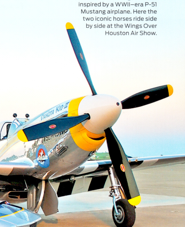
P51 from a scan of Ford sales brochure (July 2012)
Notice the look of the P51 propeller blades
Without doing some research I have no idea of the speed of WWII era propellers or their angle of attack.
Propeller dia
1.1.2 feet
Plane top speed
437 mph @ 25,000 feet
Engine power
1,490 hp takeoff 1,590 full power
Engine speed
2,400 rpm cruise, 3,000 rpm takeoff
Propeller type
fixed speed, variable pitch
Gear ratio
.479
Propeller speed
1,437 rpm @ engine speed 3,000 rpm (takeoff)
** From a poster a nice description of how air passes through an airplane propeller. Probably not too different from a wind turbine.
"What happens is air accelerates and decreases in pressure in front of the prop, then mostly experiences an increase in pressure to above ambient without much change in velocity across the "prop disk". The air then continues to accelerate again as it's pressure decreases back to ambient. The velocity of the air at the prop is about the average of the entry and exit velocities."Pitch of propellers
http://www.physicsforums.com/showthread.php?t=302688
Below is from a poster and it looks like the scenario above is about right. The pitch range at the blade tip for a P51 (or other high speed propeller plane) is shown as being in the range of 5 (takeoff) to 30 degrees (flight).
"The propeller blade is an airfoil and is subject to stalling if the AoA is too high and to compressibility effects if the speed approaches the speed of sound. When flying, the airstream that the propeller is seeing is the sum of two vectors: blade speed (perp. to where the plane is going) and plane speed. The AoA (blade angle of attack) is adjusted by changing the (propeller) pitch.=====================================================================For take-off, plane speed is zero so you do not need a big pitch, almost flat will do. At max. speed, the angle of the air flow towards the blade is high so you need a bigger pitch to keep a decent AoA.
A warning if you come up with published figures. Those are much higher than the ones that are used in X-Plane. This is because published figures use the mid radius of the blede while X-Plane uses the tip. If you see a figure like "min pitch: 20 deg, max pitch 45 deg" this will probably translate to about 5-30 (degrees of pitch at the tip)."
http://forums.x-plane.org/index.php?showtopic=26540
Wind turbine as a fan run backward --- any insight?
After thinking
a while, I came up with the idea that maybe a way to think of wind turbines
are as fans pushed backwards by the wind. A simple energy calculation
shows that if the turbine extracts 50% of the wind's kinetic energy (0.5
m v^2), the air speed leaving the turbine must be x.707 the income wind
speed (ignoring all the turbulence and inducted rotation).
My starting point was to guess that the blades, size, etc of a big 50% efficient wind turbine might be very similiar (same?) as if it were a fan (powered by a Mw motor!) oriented to blow into the wind at about 30% the wind speed. Room fans typically have air flow patterns that blows a fairly tight column of air far from the fan with an inlet pattern that is much wider and shorter. I wondered whether the wind turbine/fan idea might have a similar air flow pattern.
Playing with a room fan I could see that the blades, while deeply curved were oriented quite flat, i.e. only tilted slightly from the plane of the rotor. The part of the fan blade that cuts into the air is in the back, causing it to scoop up air. The scooped air flows across the blade to the trailing edge which is much more forward (inch or two). In this way the scooped air gains forward momentum as it crosses the blade, causing it to flow forward into the room. When I blowed on the fan (no power), it caused the blades to rotate in the opposite direction.
This line of thinking leads to this picture. Suppose our machine is a 50% efficient, 2.5 Mw wind turbine, which outputs 2 Mw at 10 m/sec wind with a tip speed of 70 m/sec (tip speed ratio = 7). Now we shut off the wind and run it as a fan. We adjust the current (2,000 A) in the PM generator/motor such that 2 Mw is pulled from the fixed grid voltage (stepped down to +1,000 V). Let's say the air blows in the direction from which the wind is to come, and blades rotate counterclockwise. A wind power calculation [Power = (1/2) (air density) x pi x (radius)^2 x (speed)^3] will probably show the air speed @ 2 Mw will be 7 m/sec, and the blade tip speed will probably be about 70 m/sec.
Now with the fan running and the current held constant (at 2,000A) in the motor/generator, let's start up the wind and let it rise to 10 m/sec. What happens? What happens (I think) is that the wind is more powerful than the fan, the wind has 4 Mw of power to the fan's 2 Mw, so the blades slow down to zero, reverse direction, and increase to 70 m/sec (clockwise) before leveling out. Meanwhile looking at the motor/generator terminals as the blades are slowing and reversing we see the PM generator voltage tracking the blade speed, reducing from +1,000V, down to 0V, and increasing up to -1,000V, all the while the current is held unchanging at 2,000A (current polarity is not changed.) Since the wind has flipped the motor/generator voltage with no change in the current the power flow has reversed. Our fan pulling 2 Mw from the grid has been transformed into a wind turbine pumping 2 Mw into the grid. It's running at the same power and speed, but it's rotation is reversed.
You can think of a wind turbine as a fan trying to blow into the wind, but the wind is so strong, that the blades (with the same shape and orientation) are being blown backwards! 2 Mw is being extracted from the 4 Mw,10 m/sec wind column entering, so the exit wind speed must be 7 msec, which has the necessary 2 Mw kinetic wind energy, since kinetic energy goes as speed squared. The exit wind having slowed down a little (-30%) must expand into a slightly larger column (+19% bigger dia) as it leaves the fan to maintain the flow.
What can we see from this picture. I suppose we might (or might not) see that some of the air flow off the blades is in the radial direction. Hard to see, but possible.
Since [power = (force x velocity)], the blades must be creating a pressure gradient that separates the incoming 10 m/sec air and outgoing 7 m/sec air, and we can calculate the pressure gradient. Force should also be calsulatable from delta p/delta t, so should tell us how quickly the momentum must change, which should tell us the width of the pressure gradient.
Power = (pressure gradient) x Area x (av) wind speed
pressure gradient = Power/(Area x (av) wind speed)
= 2 Mw/(pi x (46.5)^2 x (10 + 7)/2 m/sec
= 2 Mw/(6,789 m^2) x 8.5 m/sec
= 35 N/m^2
--------------------------------
A first cut at trying to figure out how blades interact
with air flow
This idea
and sketch are wrong. At the time I did not understand that the outer part
of the blade is flat to the wind, and the angle of attack is set by the
wind vectors and tip speed ratio.
Is this the key (my visual idea) ---
Pictures of
a large blade on a truck indicate it might be 10 or 15 meters wide. With
twist or pitch might it be 10 m deep (axially)? If air is blowing at 10
m/s, it would take one second for an air molecule to pass through the 10
meter of blade depth, and if rotation speed was say 3 sec (in reality from
Clipper data blade speed at 10 m/s is probably 90% of top speed or 4.3
sec period), then in that one second each blade sweeps through 120 degrees
of arc, so each (or most) air molecules end up hitting one of the blades?
In other words before an air molecule can sneak through the (axial depth)
of the blade, one of the blades flys by and the molecule hits it giving
up some of its energy to the blade. I made a little sketch of this
concept showing side view of the tower and blade:
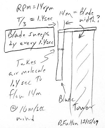
This figure is wrong --- blade is flat to wind near
tip
With this model you would want rotation speed of the blade (ideally) to vary with wind speed. This is in fact what the real efficiency curves show. Maximum efficiency is obtained when the tip speed ratio (ratio of blade tip speed to air speed) is held in a tight range near 7.
This picture also fits with making turbines large, because then a relatively thin blade is axially deep enough.
This picture also fits with how power is shed at top operational speed (25 m/s). By not allowing the blade speed to double as the wind speed doubles (12.5 m/s to 25 m/s), half (or more) of the air molecules sneak through without hitting a blade.
(update Nov 2011)=====================================================================
Wrong ---- I drew the above sketch when I was just beginning to understand wind turbines. I assumed (common assumption based on how room fans look) that the blade was rotated maybe 45 degrees or so to the wind. But I now understand the blade, at least the outer half or so, is oriented flat to the wind, the angle of attack coming from the vector sum of the wind and x7 higher tip speed. Since the output part of the blade is maybe 2 m wide, its depth is probably 1 m or less, nothing like the 14 m I show in the figure
* Turbine
layout and components video
Video with nice graphics showing the layout and components of wind turbines
http://www.youtube.com/watch?v=LNXTm7aHvWc&feature=related
*
How planes really fly
Nasa site discusses how airplanes really fly. They detail two incorrect
theories as to how lift if generated. This link has a Java applet that
it says solves the flow equations. The applet allows the attack angle to
be changed and the wing changed from a flat plate to a symmetrical airfoil
(thick front endge, thin trailing, same shape top and bottom). Playing
with this applet shows that the flat plate has 90% of the lift of the airfoil
and that that lift is almost exactly proportional to the angle (small angles).
(see also hyperphysics site, which has a long discussion)
Below notice the air in upper right, which has gone (at higher speed) over the top of the airfoil, has been accelerated rightward such that it now leads the air below it (lower right), which it previously was aligned with. The air flow pattern shows (to me) the rightward force seen by the 'over the top' air must mean (due to Newtons's 'equal and oppose reaction) the airfoil must be feeling a push leftward. This makes sense for a wind turbine. The forward force is the power producing force.
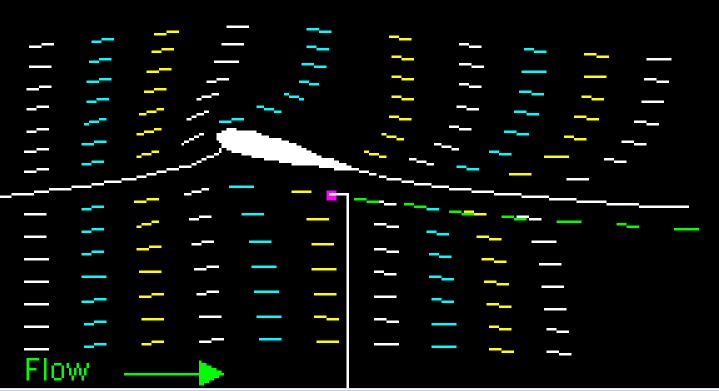
Upper and lower air flow over airfoil at 15 degree
angle of attack
NASA java applet solving flow equations
(source -- http://www.grc.nasa.gov/WWW/k-12/airplane/wrong1.html)
http://www.grc.nasa.gov/WWW/k-12/airplane/wrong2.html
* Blade dynamics
paper from a turbine manuf (Danish) Bonus (1999)
Good (if old) reference with numbers.
http://www.windmission.dk/workshop/BonusTurbine.pdf
* Managing
wind gusts
This paper by the National Energy Renewable lab shows that the turbine
can employ some tricks to increase capture energy. One problem is wind
gusts. Blade intertia is so high that it can only respond slowly, so the
paper says in the real world the turbine spends a lot of time operating
not at the peak of its tip speed ratio curve. One trick is to bias the
nominal tip speed ratio so wind guests with their high energy are more
accurately captured than wind lulls. Another trick is to vary the current
(torque) in the generator to accelerate and decelerate the blades to reach
the optimum tip speed more quickly. Tests by the NERL with their medium
size turbine showed these tricks can improve the average annual energy
out of the turbine by 5% or so.
http://www.nrel.gov/docs/fy04osti/36118.pdf
* Wind turbine
and blade design paper
40 page Carleton college paper (2005) on the phyics of turbines (long,
readable). Points out that blades must have a twist to vary the
angle of attach to compensate for variable 'relative' wind direction (vector
sum of linear wind and wind due to rotation) that varies along the span
of the blade. The local lift and drag forces are combined to yield 'torque'
and 'thrust' for the blade. Torque makes power and (I presume) thrust is
the force the tower must absorb. But control concept is dated, talks of
keeping the blade rotation rate 'constant' for the electricity. "(In practice)
only the outer most part of the blade needs to fit the chosen airfoil shape."
Even though it has many pages on blade design it doesn't address the issue of how three narrow blades can come anywhere near the efficiency of an (effective) infinite bladed betz limit.
https://dspace.lasrworks.org/bitstream/handle/10349/145/fulltext.pdf?sequence=2
* Long tutorial on aerodynamics for pilots of small planes
http://www.av8n.com/how/htm/airfoils.html#fig-90flat03p
* 'Wright brothers' discuss their studies of lift (from Nasa)
http://www.grc.nasa.gov/WWW/Wright/podcast/Podcast_Forces_Lift.m4v
***2009 study
of 5 Mw turbine by NREL (Jonkman, et al)
Includes detail turbine specs including weights
Rotor dia
126m
wind speed
11.4 m/sec @ 5 Mw rated power
Tip speed ratio
7
Period
5 sec (12.1 rpm @ 5 Mw rated power)
https://ceprofs.civil.tamu.edu/jzhang/ocen407/5MW%20Reference%20Turbine.pdf
* Master's
thesis - Umass wind turbine air flow from tower frame
===========================================================================================
Airflow picture
I've worked
long and hard to develop a picture of how air flows through a wind turbine
hoping this would give me some insight to answering two related questions:
* How is it that the efficiency of a wind turbine is so high (50%)?
* The blade circle is 90% -95% open and blades on large turbines only come
by about once a second, so
why doesn't a lot of the wind just sneak flow through the blade circle
without ever coming near a blade?
I don't have the full answer, but I have learned a few things about how air flows through a wind turbine. This comes from developing a basic understanding of the wind vectors and how this sets the angle of attack, studying air flow over airplane wings, and detail study of (four) computer simulations showing air velocity changes caused by wind turbine rotation.
Doesn't airfoil theory explain airflow patterns?Here's what I have found (assume: tower frame of reference and blade moves leftward through upward moving wind, and that the period of rotation is 3 seconds):
The short answer is no, not really. Wind turbine blades are a lot like airplane wings, both are airfoils, and airfoil theory has been around for over a century. So why can't the air flow patterns of wind turbines be figured out by looking at the theory of airfoils? A lot of the info is surely hidding there in airflow diagrams, but these are usually shown close in to the wing.The problem is that the focus of airfoil theory is almost entirely on calculating the forces on the wing, or in the case of the wind turbine on the blade. Not surprisingly there is little concern about how the air is disturbed by airplane wings flying through (with the exception of studying contrails that can affect other planes).
The wind turbine differs from a plane (powered or glider) in that its airfoil is designed to extract as much of the kinetic energy of the air as possible. For this reason a wind turbine operates at high angles of attack: 8 degrees near the tip (set by tip speed ratio of 7) rising as you go down the blade reaching about 15 degrees midway down the blade. [Power = torque x angular speed], so for high power the blades need to generate a lot of lift torque.
1) From wing air flow diagrams the air flowing up and over the back of the blade is accelerated and quickly thrown rightward about the width (chord) of the blade. This air makes nearly a step change in position perpendicular to the wind and in the opposite direction from the blade. The high flow over the back of the blade reduces air pressure on the front of the blade, which is what drives it forward.
2) None of the simulations shows the any rotation in the air after it leaves the blade circle. The air just drift rearward at what is (presumably) a reduced wind speed.
3) There are some indications (but far from definitive) that the front side of the blade briefly obstructs, slows or (partially) reflects incoming wind. The indications of this are positive pressure under airplane wings at fairly high angles of attack (wind turbines operate at 8.1 degrees angle of attack at the tip and higher further down the blade), and from one simulation a pattern sweeping with the blade of velocity changes in front of the blade circle.
4) At tip speed ratio of 7 (most modern turbines) the distance the wind flows (toward the blades) between blade passes is about 30% of the radius of the blade circle. For a highly efficient turbine this must mean that the air that interacting with (or is scooped up by) a blade each second is a volume of pie shaped air extending 120 degrees (3 sec period) and extending forward of the blades 0.30 radius.
Working some number using the Enercon E82 turbine
Below I estimate
the tip speed ratio of this turbine is about 7.3 m/sec. For 10 m/sec wind
that makes the tip speed 73 m/sec and the period 3.53 sec. For some back
of the envelope figuring let's just work with the outer half of
the blade and assume power is extracted from the inner air and outer air
with the same efficiency (probably not quite true), and figure torque and
speed for a midpoint of the outer half blade at 75% of the radius. So with
these simplification for the outer half blade at 10 m/sec we have
eff output power
1.2 Mw (400 kw/blade)
0.75 x 1.6 Mw
eff air mass (1 sec)
46,725 kg
0.75 x 62,300 kg
eff air mass (blade pass)
54,980 kg
3.53 sec/3 x 46,725 kg
eff radius arm
30.75 m
(0.75 x 41m)
period
3.53 sec
eff (tip) speed ratio
5.48 (54.8 m/sec)
0.75 x 7.3
eff angular speed
1.78 rad/sec
2pi/3.53 sec
Since [power = torque x angular speed] and [torque = radius x force], we can figure the torque and tangential component of force (power producing force) in each blade.
tangential force = power/(radius x angular speed)
= 400 x 10^3 watts/(30 .75 m x 1.78 rad/sec)
= 7.3 x 10^3 N (per blade)
The wind component seen by the blade due to its motion is 54.8 m/sec, while the wind is 10 m/sec. This makes the angle of attack tan^-1 (1/5.48) = 10.34 degrees. The ratio of forces is the eff (tip) speed ratio or 5.48. Hence
force component
toward tower = 5.48 x 7.3 x 10^3 N
= 40.0 x 10^3 N (per blade)
lift force
= sqr{40^2 + 7.3^2} x 10^3
= 40.66 x 10^3 N (per blade)
A basic equation for force is [delta p/delta t] or the change in momemtum (mass x velocity) per unit time. A think we can work with the two force components separately. We have the mass of air, and the delta time (period), so using the tower force we can find (I hope) a delta wind velocity.
force = delta p/delta time
= mass x delta vel/delta time
We have the (tower) force per blade. The best delta time to use is the time betwen blade passes 3.53 sec period/3 = 1.177 sec. The eff mass of air moving through the blade circle in the time of a blade pass in the table above is handled by three blades, so we need to divide by three to the the mass of air handled by one blade
delta vel = force x delta time/mass
= tower force x 1 sec/ (1/3) eff mass
= 40.0 x 10^3 N x 1.177 sec/(1/3 x 54,980 kg)
= 2.57 m/sec
(or 25.7% of 10m/sec wind)
pretty good
A slow down of 10 m/sec wind by 2.57 m/sec to 7.43 m/sec is pretty damn close to 7.07 m/sec air which has lost 50% of its kinetic energy. A slow down of 2.57 m/sec yielding 7.43 m/sec implies a loss of kinetic energy of 55%. Pretty good.
------------
Idea
In trying
to solve the 50% efficiency mystery I kept looking for the mechanism to
extract energy from the air before it passed through the blade circle.
It just seemed obvious to me that once the air was downwind of blades no
energy transfer to the blades was possible, but now I think I see that
this may not be (completely) true.
Airfoil pressure charts show that more than half an airfoils lift force from a lowered dynamic pressure region as the air's speed increases to go up and over the blunt front surface. In an airplane wing this is (relative) negative pressure on the top of the airfoil (holding the plane up), but in a wind turbine is (relative) negative pressure on the back side (downwind side) behind the blade. The focus in airfoil theory is always the force on the airfoil, how if pressure is lowered on one side then the airfoil, then the airfoil is, in effect pushed, toward the negative pressure region by the air on the other side of the airfoil.
But surely the air on the other side of the negative pressure region must be pushed toward the negative pressure region too. In other words air at normal pressure all around the region of dynamic pressure region adjacent to the airfoil (created by higher speed flow over a rounded surface) must be pushing toward it to equalize the pressure.
In a wind turbine this might provide a mechanism to extract wind energy from air that has already passed through the blade circle. When a blade slices through, wind that has (just) passed through the blade circle between blades will now feel a force pushing the air backwards toward the blade circle. The air does not reverse direction, but a backward [force x time] impulse can lower its velocity, which must mean it has lost kinetic energy. In other words a mechanism to transfer momentum from (slighly) downsteam to the blade.
Is this the
answer to the mystery of why a lot of air doesn't sneak through the blade
circle without coming near a blade? The answer being the air does pass
through at the wind speed, but while it is still within 30% radius of the
blade circle a blade is guaranteed to come by, and its downsteam negative
pressure region will exert a backward force (force toward the blade circle)
on the downsteam air slowing it and robbing it of energy.
force = ma
force = mass x (delta vel/delta time)
force x delta time = mass x delta vel
= delta momentum
Other air that 'hit's (comes near) the front side of the
airfoil is slowed down and also tranfers momentum to the blade.
next calculate lift force from lift equation
--------------------------------------------------------------
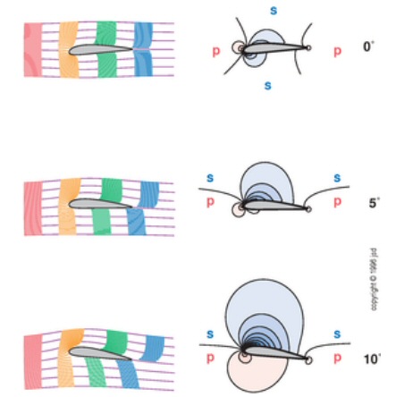
Dynamic pressure. Air pressure changes relative to local (stream) pressure are often called 'gauge pressure.
Q = ½ x density x vel^2
= ½ × 1.2250 kg/m3 × (51.44 m/s)2
= 1621 pascals (N/m^2)
= 0.235 PSI
= 0.016 Atm (1.6% of atmospheric pressure for 51m/sec.
-- As we saw
in the bottom panel of figure 3.7, at high angles of attack a wing is extremely
effective at speeding up the air above the wing and retarding the air below
the wing. The maximum local velocity above the wing can be more than twice
the free-stream velocity. This creates a negative pressure (suction) of
more than 3 Q. (worst case 3Q would be about 15% of atmospheric pressure
at a tip speed of 7 at 12.5 m/sec wind)
---------------------------------------------------------------
Airfoil pressure
http://www.mh-aerotools.de/airfoils/velocitydistributions.htm
http://home.anadolu.edu.tr/~mcavcar/hyo301/14_PressureDistribution.pdf
====================================================================================
Blade pressure
Questions
After I leaned
a little bit about aerodynamics and had calculated the dynamic pressure
of the blades and the average Betz pressure, it began to look like the
low and high pressure regions that travel with the rotating blades
were somehow being averaged over the whole blade circle to slow down most
of the incoming airstream, but how? Particularly puzzling was how
the strong negative pressure region behind the blade was slowing
down the incoming wind. And how is it that this slowed air transfers so
much of its momentum to the occasional passing narrow blade? In short,
was there a picture for a non-aerodynamicist that would explain, or at
least suggest, how wind turbines really
work?
Idea --- negative pressure can pull back on the air
already passed through
One day I suddenly
realized that how the negative pressure region behind the blade might be
slowing the exiting airstream. Airfoil analysis always focuses on the lift
forces it creates on the airfoil (blade), but just as a high pressure
gas bubble region (say caused by a chemical explosive) pushes outward in
all directions, a negative pressure region must be 'pulling' inward in
all directions. So the air downstream of the negative pressure region
must feel a force pushing it back towards the blade circle. In other
words here was a possible way to extract energy from wind that has already
snuck through the blade circle between blades!
force = ma = mass x delta velocity/delta timeMy qualitative picture of how a wind turbine really works
force x delta time = mass x delta velocity (impulse)
= delta momentum
Thus on both sides of the blade is a momentum transfer mechanism between the air and the blade. Here is a possible mechanism from smoothing out the high blade dynamic pressure. If as a blade sweeps by a region of air sees its high pressure regions for say 2% of the time, this is equivalent to a x50 lower pressure applied 100% of the time over the blade circle (as the betz analysis assumes). On both sides of the blade the air is slowed, so it must be losing both momentum and kinetic energy, and in a wind turbine, unlike an airplane wing, the blade moves in the direction of the forces on it, so absorbs energy.
So the picture is the low and high pressure regions adjacent to the sweeping blades produce a sweeping pattern of momentum transfers (high force x short delta time) and energy transfers from the air on both sides of the blade to the blade.
Simulation pressure profile
Below left
is a wind (surface) pressure profile from NASA Foil II simulator (beta
1.4). This simulation is for airplane wings, but it can tell us about wind
turbine airfoils too! I set the angle of attack to 8.1 degree and the airspeed
at 70 m/sec. This are the conditions that would be seen near the tip of
the blade in winds of 10 m/sec (22 mph), where a turbine will be outputting
about 80% of its rated power and be near its efficiency peak. For a plane
wing the larger negative pressure is along the top surface and the smaller
positive pressure along the bottom surface, both exert an upward force
on the wing, which is adjusted to just balance gravity in level flight.
In a wind turbine the combined wind speed and x7 blade rotation speed cause
the air to rush more quickly over the airfoil's (rounded) back side or
downstream side. Hence the larger negative pressure region is always
downstream and the smaller positive pressure upstream.
Just like in a wing, where the positive pressure (under the wing) and negative pressure (above the wing) add to keep the plane aloft, in a wind turbine the two pressure terms also add with the larger vector component of force acting to deflect the blade toward the tower while the smaller vector component of force acts (pushing and pulling presumably) on the blade in its direction of motion, thus doing work on the blade as it cuts perpendicularly through the air flow.
The figure below right are airplane wing pressure diagrams that I rotated about 90 degrees. With the rotation they now show the pressure patterns for a wind turbine blade slicing downward with the wind coming from the left. The positive pressure is upstream and the much larger negative pressure is downstream. The tip of the blade would have an angle of attack of 8.1 degree (roughly midway between the two diagrams). Going down the blade the air speed slows increasing the angle of angle, so the left (10 degree) pressure diagram represents blade pressures about 20% down from the tip.
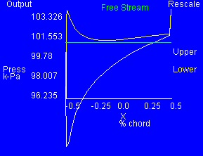 .
. 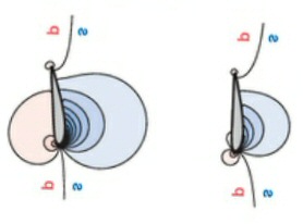
left:angle of attack = 8.2 degree
right: 10 degree, 5 degree angle of attack
air vel = 70 m/sec
wind from left, moving downward
area = 9.3 m^2
pressure isobars = 0.2 dynamic pressure
lift =
26,700 newtons
negative pressure (blue, downstream)
lift coefficient = ?
positive pressure (pink, upstream)
baseline pressure = 101.26 pascal (newton/m^2)
deta pressure (peak) = +2 kpascal and -8 kpascal (round
numbers)
Av delta pressure (total) = 26.7 knewtons/9.3 m^2
= 2.87 kpascal (approx, assumes lift coefficient = 1)
The two images above look different, but they are consistent. The left (blue) image is surface pressure along the chord of the wing. The right (white) image shows pressure isobars extending out into space on both sides of the airfoil. In both images the negative pressure is much higher than the positive pressure, and in both images pressures are much higher near the (blunt) leading edge of the airfoil.
Calculating dynamic pressure
It useful
to look at pressure profiles normalized (in terms of dynamic pressure).
[Dynamic pressure (in pascals) = (1/2) x air density (in kg/m^3) x vel
(in m/sec)^2]
P dyn = (1/2) x 1.225 kg/m^3 x (70 m/sec)^2
= 3,000 pascal (newton/m^2)
= 3.0 kpascal
Dynamic pressure about same as simulation average wing
pressure
From the graph we see
the (delta) peak pressure on the lower (or upstream) surface is
about +2 kpascal and for the upper (or downstream) surface is about -8
kpascal. (These look like reasonable numbers as they are in the ballpark
of pressure profiles I see in other references.). From the lift value of
the simulation (26,700 newtons and assuming the lift coefficient is about
1) the average dynamic pressure across the wing chord is [26.7 knewtons/9.3
m^2] = 3 kpascal. Eyeballing the pressure vs chord above I can believe
the average over the chord is about 1/3th of the peak. This would make
the average wing pressure from the simulation (3.33 kpascal crudely) pretty
much the same as the calculated dynamic pressure (3 pascal) at 70 m/sec.
Visuallizing the wind turbine air flow around the blades
For me to
think (qualitatively) that I 'really' understand how a high speed perpendicula
'wing' is extracting wind energy I want to be able to visualize airflow
as a wing cuts through. I think then I might be able to gain some understanding
of how the wind is doing work on the blade and itself losing speed (&
kinetic energy). Particularly troubling for a long time was how to visuallize
how the air that has already passed through the blade circle could do work
on the blades. But this must be the case because the dominant force on
a plane wing is the negative pressure over the tipped up rounded side,
which in a wind turbine is the downstream side.
Such an air flow could easily come out of a java airfoil simulator set up for wind turbines, but in spite of a many searches nothing like this seem to exist in the public domain. There are some videos of wind turbine downstream air flow, but none of them have the detail to show what is really happening around the blades. So back to the plane wing simulator, with some reorientation we can get some hints from it. Here is the wing/airfoil figure from above rotated (and mirrored) so that it represents a wind turbine bladed slicing vertically downward with wind coming from left.
Frame of reference
The difficulty in
using this airflow image is that it's drawn for a plane, where the frame
of reference is the airfoil, so the flow arrows represent the airflow 'as
seen from' the wing. But to think about a wind turbine I would like to
see the wind flow indicated 'as seen from' the ground, which is the natural
reference for a wind turbine. Maybe this is too complex because there are
two object in motion (wind and blade) in two orientations and at substantially
different speeds (x7), but I would think a 3d video would work. Maybe a
frame relative to the wind would be useful. (I suspect this is the frame
of reference being used by the wind turbine 'wake' simulations.)
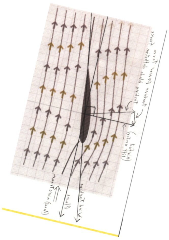
But with some imagination I think a rotated plane airflow diagram (above) can give us some clues. Note here the incoming (left side) wind arrows are tipped a little from the vertical. A vector combination of a large vertical flow (due to the motion downward of the blade) and a smaller (1/7th) horizontal flow (due to the wind). Relative to the ground we need to use our imagination to ignore the vertical (blade motion) term and 'see' only the (horizontal) wind term.
The upper half of the image shows the airflow just after the blade has cut through. Notice the airflow arrow downstream are more vertical than those upstream. This is key. This shows that the passage of the blade has reduced the (horizontal) wind speed, the wind has lost energy.
The lower half of the image shows how the wind flow changes as the blade approaches and cuts through. We can see that some air just in front of the blade is thrown (briefly) forward (arrows tipped more) to get out the way of the approaching blade, and then that air closest to the downstream surface of the blade is accelerated (briefly) upward (shown by wider spacing between the arrows). This air speeding up and over the (rounded) airfoil surface is what (via the bernulli effect) causes the dominant (negative) pressure region that travels along with the blade on its downstream side.
Figuring the forces
Elastic collisions
As background
for an understanding of how air at the molecular level does work on the
blade, I decided I would do a freshman physics calculation of two masses
of different masses colliding elastically. An elastic collision is where
the masses 'bounce off' one another such that no energy is lost in the
collision, but energy can be transferred from one mass to the other.
Thought it would be simple, just conservation of mass and conservation of energy for system, but after a few minutes and a page full of equations I gave up and looked it up and also played with some applets. References pointed out the math is messy (since energy goes as vel^2), but there is trick to simplify the math. The trick is to recognize that in a moving frame the collision results would be the same, so transform to a frame where one body is initially not moving, do the calculation and transform back. In the case of an air molecule (N2 or O2) colliding with the moving blade the calculation is further simplified in that the blade velocity is unchanged by a single air molecule hitting it since the mass ratio is effectively infinite.
The solution to this 'reduced' problem can be visualized without writing any equations. In the frame of the (moving) blade an air molecule comes in and bounces off. In the limit of [blade mass >> molecule mass] the magnitude of the molecule velocity is unchanged, however its sign reverses. Thus if the blade is not moving we can see that air molecules have the same kinetic energy after the collision as before, so no work is done on the blade.
However, if the blade is moving the situation is different. Riding on the blade (moving frame) the collision looks the same with the blade moving as not moving, but when transformed to a fixed frame we can see the air molecule does lose energy to the blade. There is a speed where a molecule loses all its (thermal) kinetic energy to the blade. This is when the air molecule come in at twice the speed of the blade. Then the relative speed is the same as the blade speed, so post collision the molecule has no motion and no kinetic energy remaining, having transferred it all to the blade. (A somewhat similar thing happens in the desktop toy where a ball on a string hits a bunch of identical balls on strings. The incoming ball surprisingly stops dead having transferred all its kinetic energy to the outgoing ball.)
Air molecule speeds
What is the
thermal speed of air molecules anyway? I had no idea. Turns out it is a
broad curve peaking around 500 m/sec, much faster than 70 m/sec of a moving
blade. So my thinking is if a moving blade has negative pressure region
near its leading edge the (relatively higher pressure) molecules on the
trailing edge are moving fast enough to 'push' the blade forward by transferring
(thermal) kinetic energy to the blade. Not sure how this meshes with wind
energy, but I suspect it comes out in the wash, since wind energy of 10
m/sec at the molecular level is just a small bias to much higher (500 m/sec)
thermal velocities.
Gas molecular energyAir molecules hitting at moving blade
The equation for the peak speed shows it proportional to (absolute) temperature and inversely proportional to mass. This means the kinetic energy of a gas molecule at a given temperature is exactly the same independent of the mass of the molecule. All gas molecules at room temperature have the same kinetic energy, so hydrogen molecules move much faster (about x5) than N2 molecules. Also the energy per gas molecule is linearly proportional to absolute temperature. (I guess this is why an ideal gas makes sense, pressure and work from a mole of gas molecules of any type (any mass) will be pretty much the same.)
Here's a first draft sketch of energy loss vs air molecule speed for blade speeds of 70 m/sec (tip of blade) and 35 m/sec (halfway down blade).
![]()
Obviously an
air molecule has to be moving at a minimum 70 m/sec to catch up with a
slicing blade moving at 70 m/sec to hit its trailing edge. At 140 m/sec
molecular speed an air molecule stops dead after hitting the trailing edge
of a 70 m/sec blade since it loses all its thermal energy. At 500 m/sec,
which is how fast air molecules typically move, air molecules still give
up about half their thermal kinetic energy to the blade since only 52%
of their kinetic remains {0.52 = [(500 m/sec - 140 m/sec)/500 m/sec]^2}.
At the molecular level kinetic energy from heat (at 500 m/sec) is vastly
higher than wind energy figured at 10/sec, so bottom line: air molecules
are easily moving fast enough, and have enough thermal kinetic energy,
to 'push on' and transfer huge amounts of wind energy to a 70 m/sec speed
blade.