(source -- http://www.antiqueradios.com/forums/viewtopic.php?p=2368555)
(source -- http://www.antiqueradios.com/forums/viewtopic.php?p=2368555)
Restored Philco 511
My unrestored Philco
511
With
dust removed from tubes and transformers
For sale cheap Philco model 511 vintage radio from
1928 (dec 2016)
In very good
condition, complete (no missing tubes), unrestored (except some of the
dust cleaned off the tubes and transformers), no obvious dings, just a
few scratches on cover (which nearly all 511s have because that is where
the speaker normally sat). Only two owners, first owner was an elderly
neighbor of mine who I presume bought it new in 1928 and used it 30 years
before giving it to me a kid in HS around 1958. As an EE engineer I always
planned to get to it one day, but never did, so it has never been hacked
or tampered with just open up and gathering dust. No rust since it has
always been used and stored inside. I not 100% sure, but I think it was
working when I acquired it in the 50s, but it has not been powered up since.
This is sort of irrelevant anyways, since radios of this vintage are more
for display than use since they are early TRF (tuned radio frequency) designs
that preceded the adoption of superheterodyne for commercial use. Included
in this essay are the schematics for the 511 that I found online and look
like they match the hardware.
I own a Philco model 511 vintage radio from 1928
A little essay on
the Philco model 511, a vintage radio from 1928. While I am not a collector
or antique guy, by happenstance I own one of these radios. I have owned
it for over 50 years, but until recently I didn't know what I had. When
I was in high school, an elderly neighbor knowing I was a kid interested
in electronics gave it to me. In 1958 when I got it, it would have been
thirty years old. I'm pretty sure it was working at that time, and I have
a vague memory of plugging it once. Is it working now? Who knows, it hasn't
been plugged in in over fifty years, but it's all there with no apparent
damage except for the speaker cloth.
Later after becoming an electrical design engineer I thought of this radio as an opportunity for me to learn about early radio design and about tubes. But it was one of those projects I never got around to while working, and after retirement I lost my lab and had no space to work on it, so it has just lain in the corner of my room all these years. Prior to the internet there was no easy way to research an old radio. The nameplate says Philco and I might have written Philco a letter (I remember I planned to, whether I did or not I don't remember), but the chance of getting any information from a manufacturer decades after a product is manufactured is slim.
A couple of weeks ago I brushed away the dust and photographed the nameplate, and saw it was clearly marked Philco model 511, and to my surprise when I entered this into Google, a wealth of information came up. It turns out that being made in the 1920s and being the first production radio from Philco, it is something of a classic. The model 511 was Philco's entry into the radio business introduced in mid-1928, and from details of the nameplate I have the 1928 model. In the 30s and 40s table top radios came in a wide variety of beautiful wood cases, and these are highly prized by antique radio collectors. My Philco is from an earlier era, the case is metal, even though it is technically a table top, it is large (2 ft wide x 1 ft deep) and heavy and the speaker (also large and heavy) is separate. It was pretty expensive at the time selling for $115, speaker and tubes (or so I read) were sold separately.
Restored Philco 511
Here's what
a restored Philco 511 looks like.
(source -- http://www.antiqueradios.com/forums/viewtopic.php?p=2368555)
(source -- http://www.antiqueradios.com/forums/viewtopic.php?p=2368555)
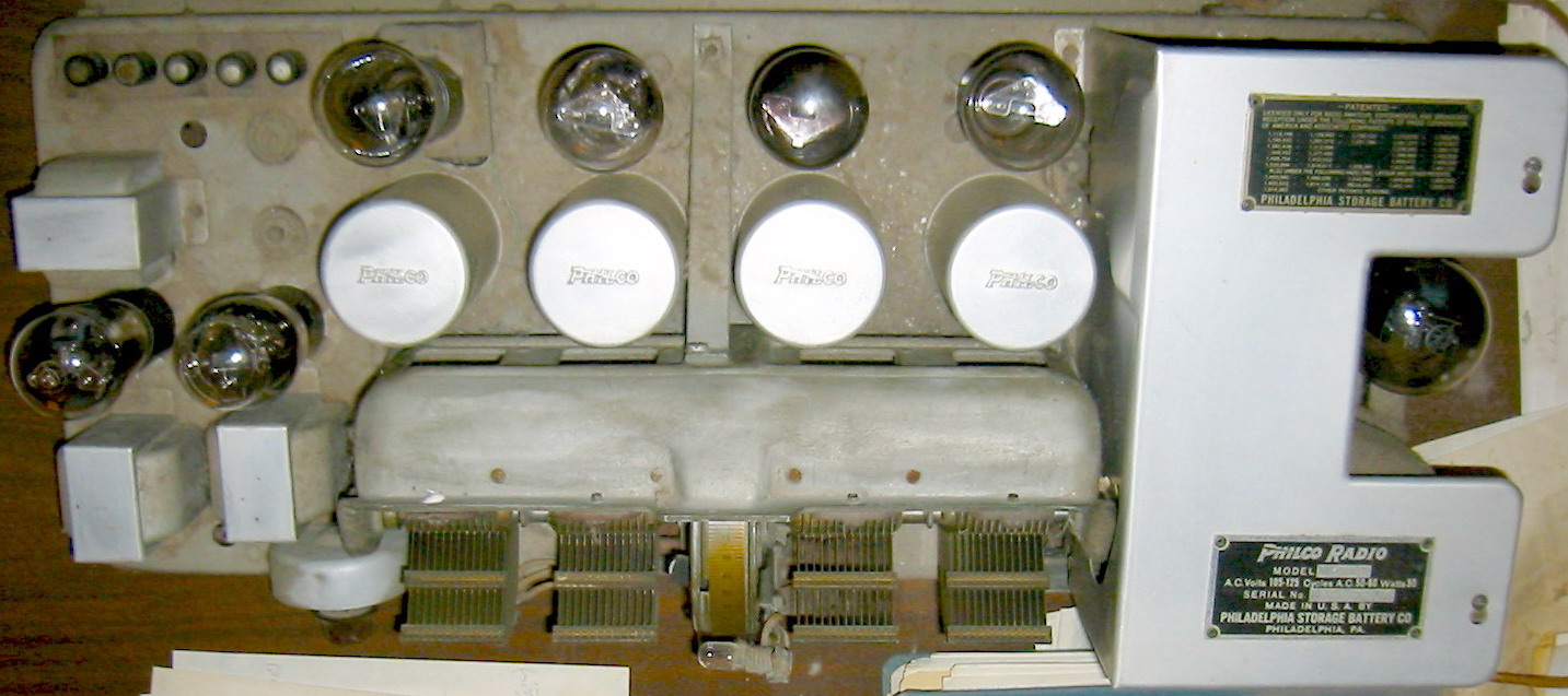
From a modern perspective the underside of a 1920s radio has relatively few parts. It's mostly just wiring. This was before the era of PC boards so everything had to be hand soldered when it was manufactured.
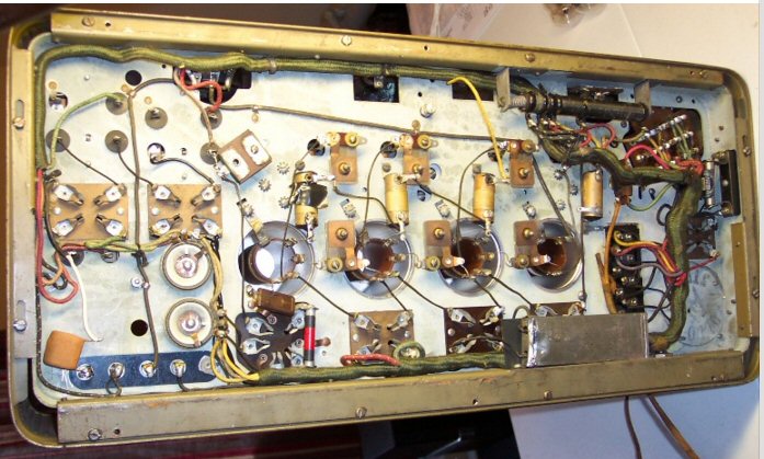
From this view you can see into the four metal cans
behind the large ganged tuning capacitor
and see they contain interstage RF (air core) coupling
transformers
(source -- http://www.antiqueradios.com/forums/viewtopic.php?p=2368555)
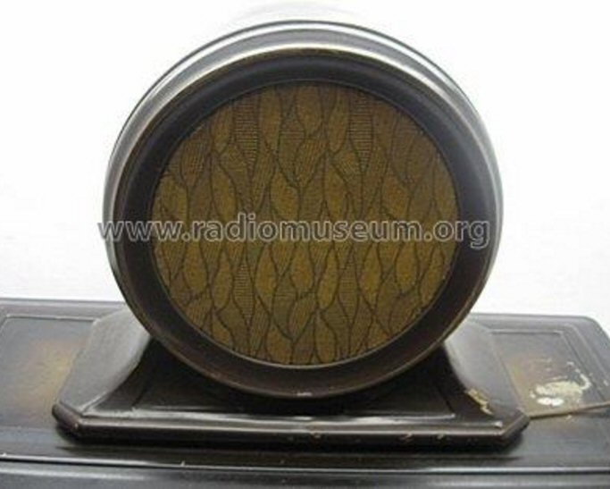
Philco 511 matching speaker, model 211
sold separately ($25)
(source -- http://radiomuseum.org/r/philco_211_2.html)
Info on restoration of a 511
Antique Radio
Forum link below has lots of information and pictures that detail how to
restore a Philco 511, including what to do about replacing some of the
old capacitors that have probably dried out with modern capacitors.
http://www.antiqueradios.com/forums/viewtopic.php?p=2368555)
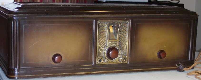
My unrestored
Philco 511
Here are photos
of my Philco 511 as it lays in the corner. It's complete with all its tubes,
but dusty and in need of some serious elbow grease to burnish up the chassis.
The case has no dents with some light to moderate scratches on the cover.
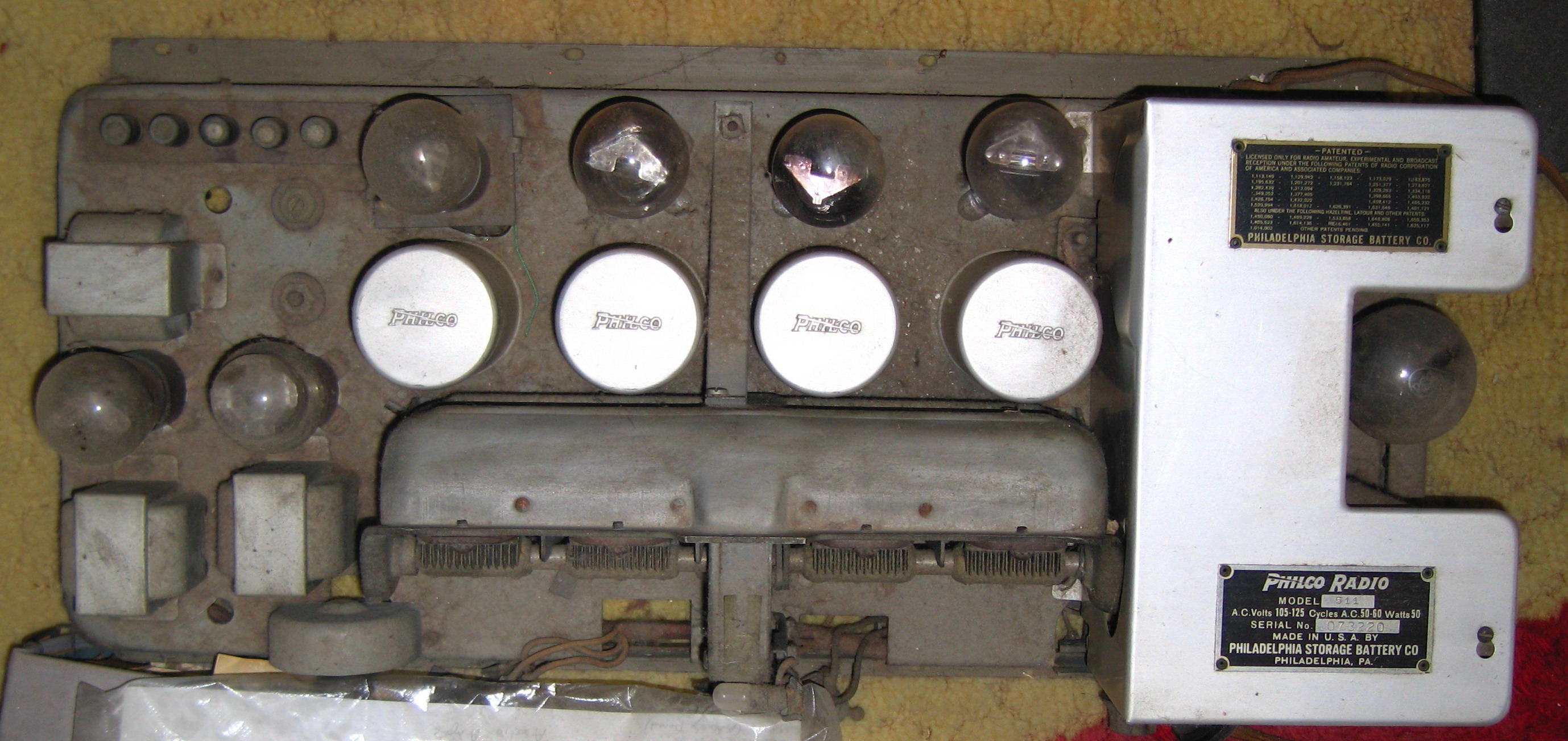
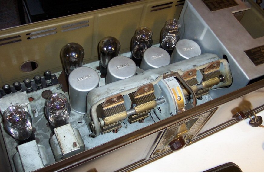
my Philco 511 out of its case and dusty
(complete with all tubes)
The power supply is right with the metal shield covering
its large magnetics.
My
Philco 511 partially cleaned up
Here my 511
after a little elbow grease has removed the dust and some of the grime
from tubes, transformers, tuning capacitor and chassis. The chassis in
particular would benefit from a through buffing.
 .
.  .
. 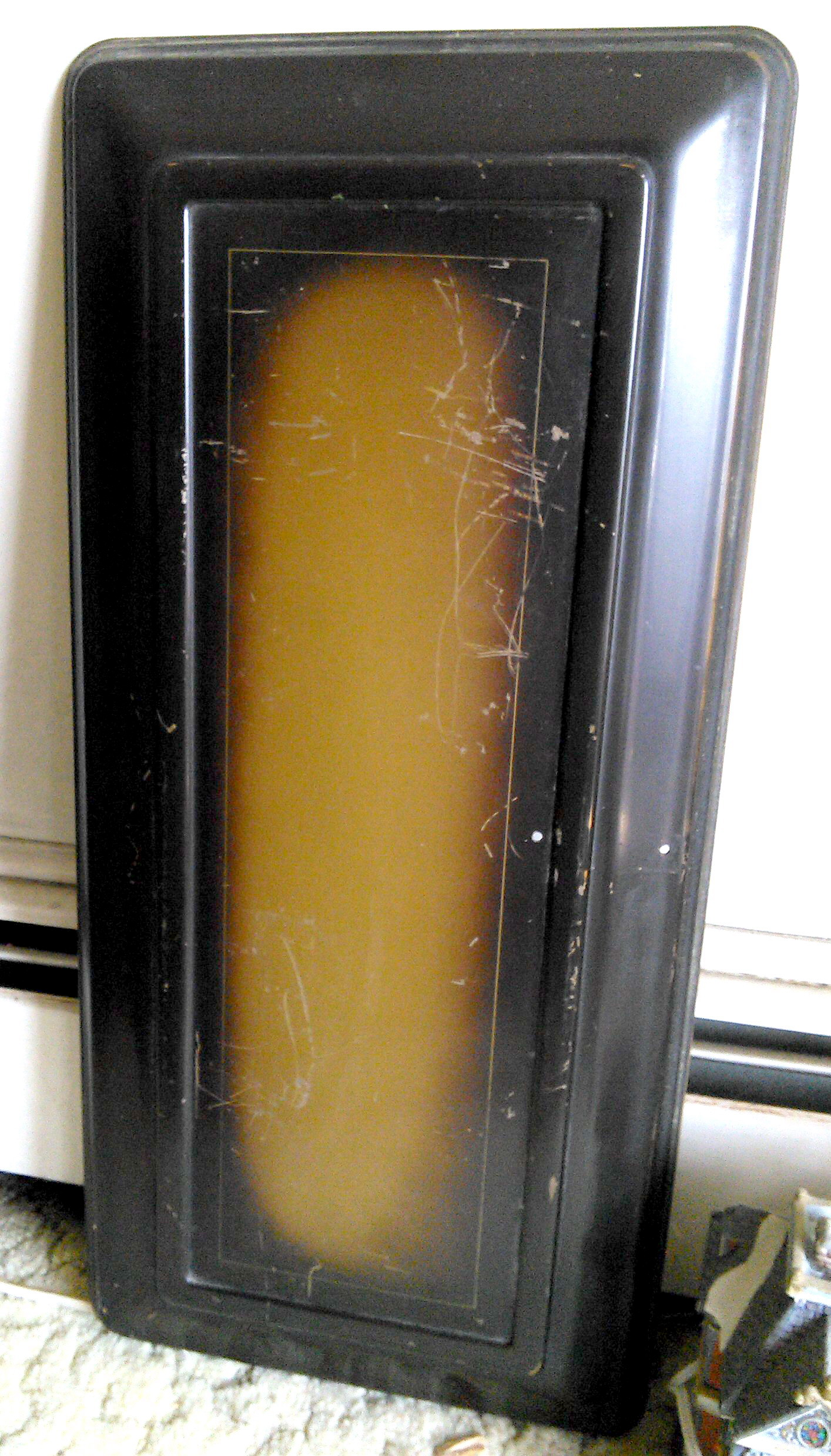
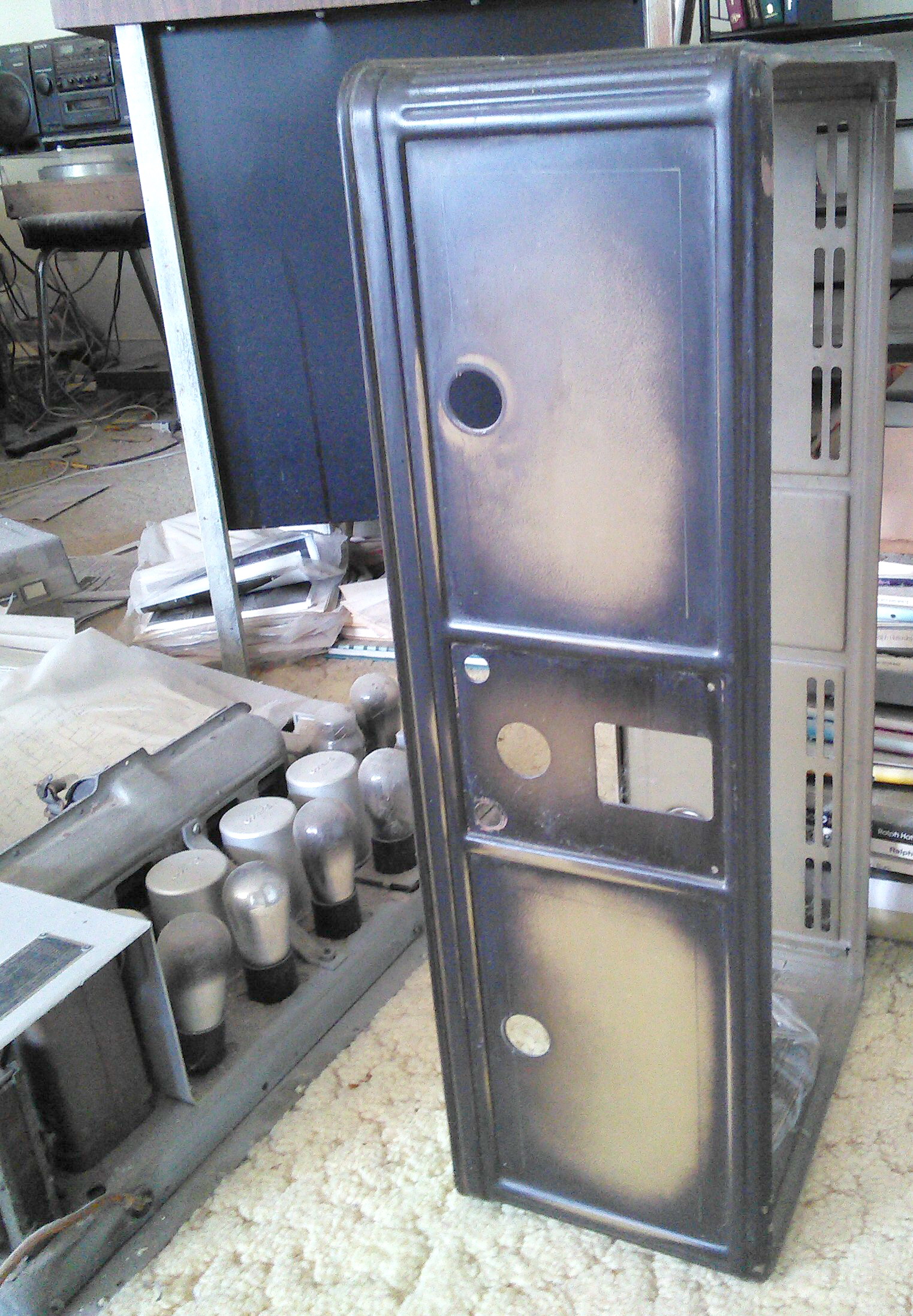
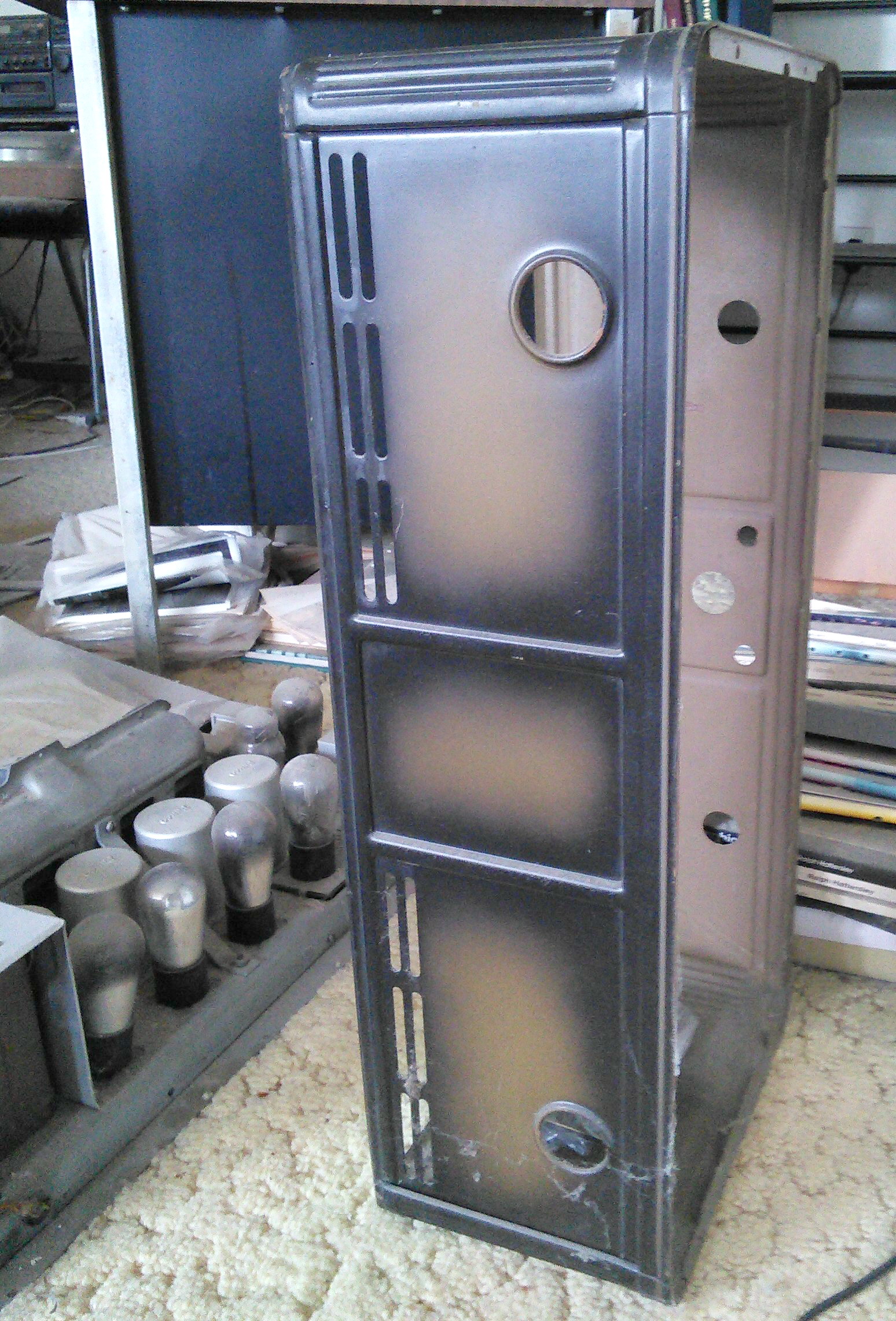
views of my 511 metal case
(Note almost all model 511s have some scratching of
the case top
because that's where the speaker normally sits)
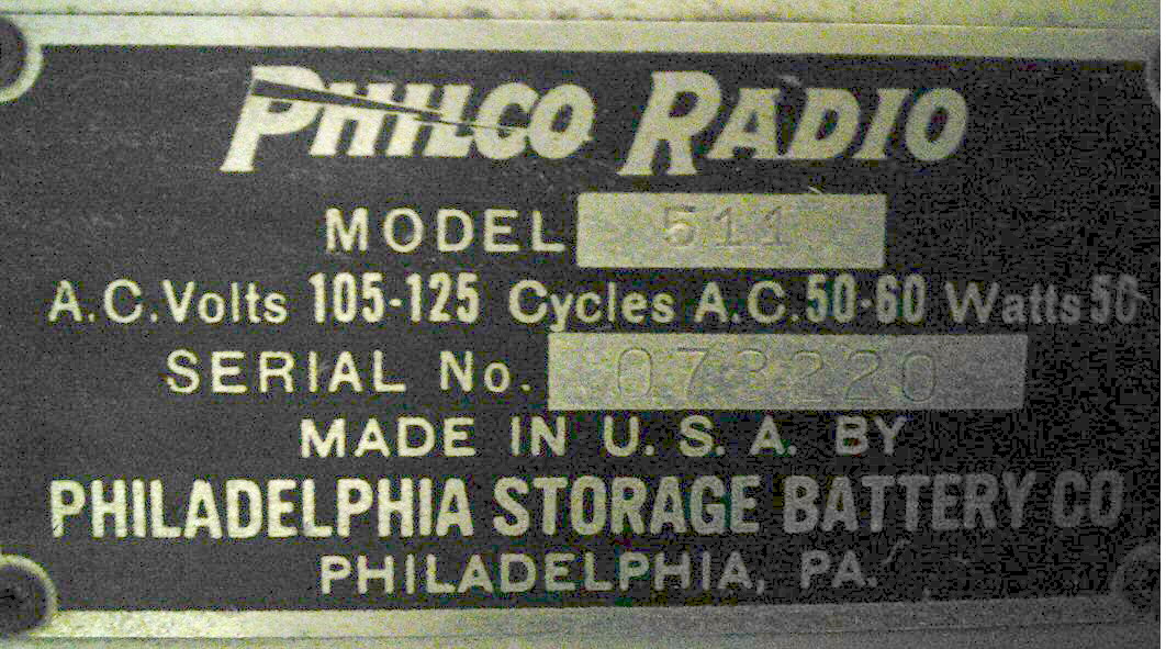
closeup of my nameplate
(Note the lightning bolt through Philco. I read this
is an indication that this is a 1928 model.)
 .
. 
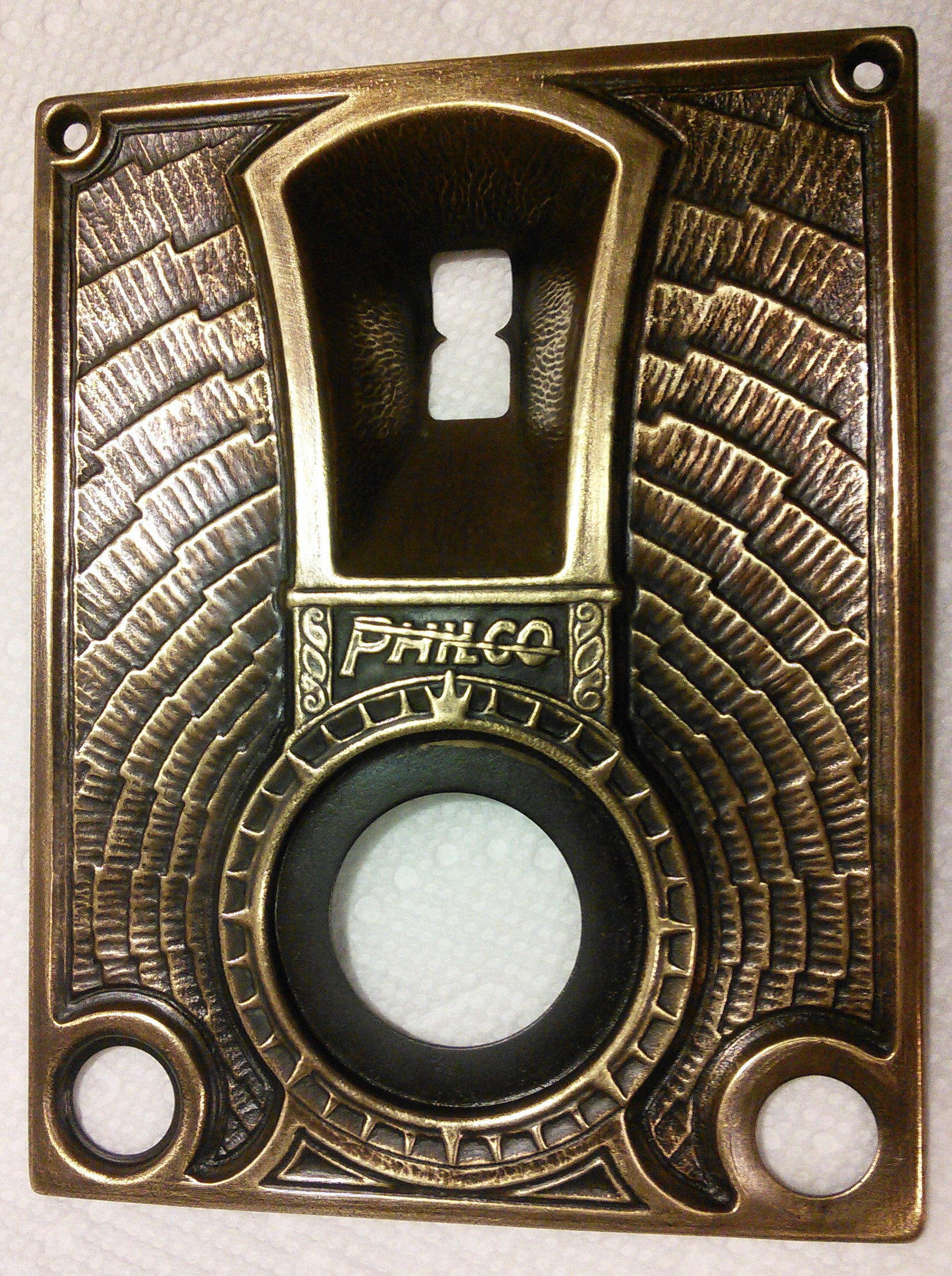
(left)
faceplate of my 511 (buffed up)
(tuning dial window, tuning knob center,
headphone jack lower left, on/off toggle switch lower
right)
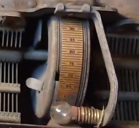
(right) tuning dial (0 to 100) (scn capture)
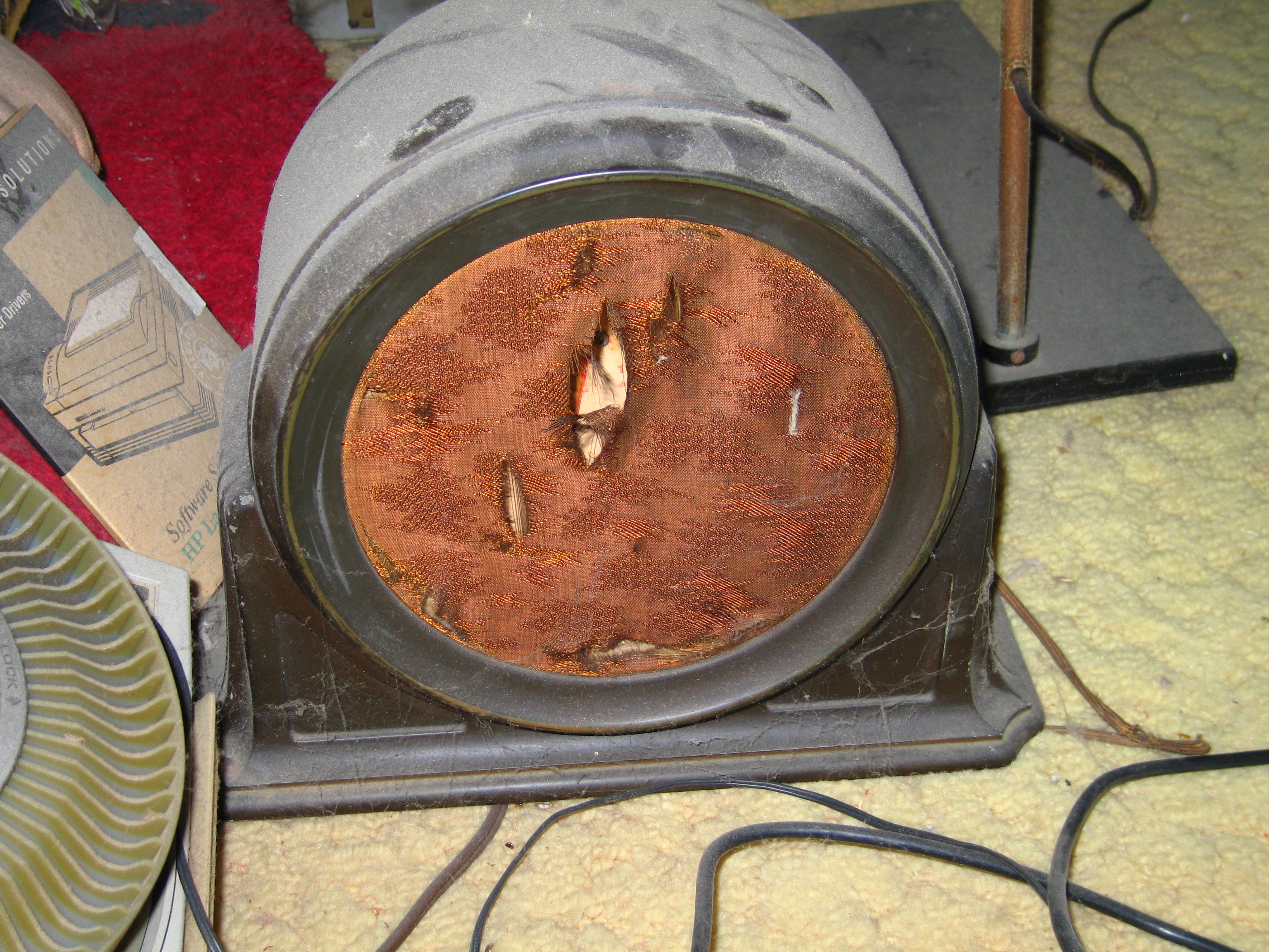
my matching 211 speaker
(face cloth has some holes)
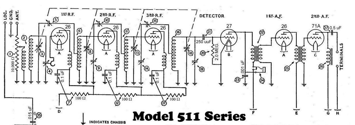
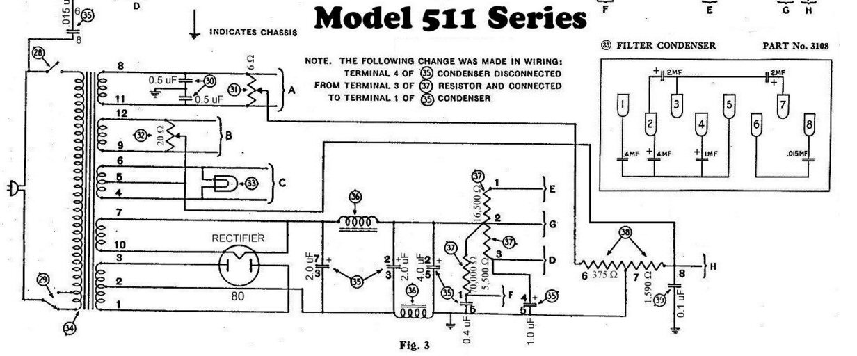
Schematic of Philco 511
To show more
detail I captured the schematic in two images. It divides nicely with the
RF, detector and audio in the first image and the 115 VAC, 60 hz power
supply in the second image.
This is a 'tuned radio frequency' design, which was common in the 1920s. By the 1930s the turned radio frequency design was replaced by the superheterodyne which had superior selectivity. The superheterodyne had been invented by Armstrong in 1919, and while it was used early in military radios, Wikipedia says it was slow to penetrate the commercial radio market because in the 1920s it was more expensive to build. In a tuned radio frequency receiver to change the channel the so-called 'pass-band' of each of the three RF amplifiers has to be shifted through the entire AM band (roughly 500 khz to 1,500 khz at the time). This tuning is done by four variable air plate capacitors ganged together on the same shaft (indicated in the schematic (below) by the dotted line). The chassis photo shows this four ganged tuning capacitor is quite large, taking up a good chuck of the chassis area.
(source --- http://www.philcoradio.com/tech/images/511.jpg)
Note these 1920's tubes (excluding detector 27 and rectifier 80) are all simple triodes. The external model 211 speaker connects to 'Terminals' (right). The schematic shows the speaker is driven through a 0.5 uf cap, which isolates it from the DC plate voltage of tube 71A (2nd Audio Frequency amplifier). I've seen this Plilco speaker referred to as a high impedance speaker, and it must be since the coupling capacitor (27) is small (0.5 uf). The speaker impedance would need to be 500 ohms or higher to get any reasonable low end response.
(source --- http://www.philcoradio.com/tech/images/511.jpg)
The power supply has a large 50/60 hz, 115 VAC transformer with many secondary taps. The A, B, C secondaries provide low voltages for the tube filaments, and secondary C also powers the incondescent pilot light. The remaining windings drive the rectifier tube 80, whose output with filtering provides high voltage DC (80V?) for the plates of the tubes. The transformer and two large filter inductors (36) are mounted on top of the chassis under a metal shield adjacent to rectifier tube 80.
Testing --- Just plug it in?
It's not wise to
willy-nilly just plug in a radio this old that's been sitting around for
decades to see if it works. Something could easily burn up or catch on
fire. One way to approach an old set like this is to first remove and check
the tubes on a tube tester, but since tube tester are hard to find these
days at least check the resistance of the filaments with an ohmmeter. It
goes without saying that a good visual check of the underside is a must.
Look for burned or cracked resistors, bad solder joints and wiring integrity.
With all the tubes removed a small external current limited external DC
power supply is helpful to check the integrity of the wiring and the high
voltage isolation of the capacitors. Electrolytic capacitors in the power
supply section are of particular concern with a radio this old (almost
90 years) as this type of capacitor tends to deteriorate over time by drying
out, so they might need to be replaced. Whether tubes this old hold their
vacuum I don't know, but there seems to be an active market in old tubes,
so that would argue they do hold their vacuum. When I was a kid, local
drug stores had tube testers, but I don't have a clue where to find a tube
tester in 2016.
A quick check of the tubes and power transformer, which I saw on a restore video, is just pull the rectifier tube, and then bring up the AC voltage gradually with a variac while watching its AC output current with a multimeter. This makes sense. With rectifier tube out there's no high voltage, but the transformer still powers the tube filaments, so at full 115 VAC input to the radio, so they all should be seen to glow. Note the schematic shows that excluding the rectifier tube (80) all the tubes are powered by one of three filament voltages labelled A, B, C, and since these filament voltages come directly off the power transformer, they will be low voltage AC. The schematic also shows the tubes filaments are wired in parallel to its appropriate transformer winding, so current from the variac will flow even if one or two filaments are open. Hence the best check for the tube filaments is to look for a glow from each filament and over time a warming of the tube. If no glow, then double check the filament resistance with an ohmmeter and verify that there is low voltage AC filament voltage at the tube socket. An open filament means a bad tube that has to be replaced. If the tube filaments are OK, and the vacuums have held then there's a good chance the tubes will work.
The trickiest parts to test are probably the high voltage capacitors, especially the (polarized) electrolytics. While a capacitance meter can check capacitance, it doesn't usually verify that the capacitor can safely sustain high voltage. A quick but effective test of the isolation of all the high voltage capacitors and wiring in the power supply and plate circuit can be done with all the tubes out using a small external DC power supply with current limiting turned down. Connect it across the first capatitor at the rectifier tube output (20 uf), observing polarity, which will insure that all the DC plate voltages (D,E, G, and H) come up as ratioed. Slowly bring up the supply voltage to the operating level monitoring plate voltage G (available at the plate terminal of the 2nd audio amplifier tube 71A) to 80VDC, or better to 100VDC to show there is some margin, and let it sit a while while monitoring the supply current. Short the terminals that go to the speaker, so the speaker isolation capacitor is also checked. I see many vintage radio restorers routinely replace electrolytic capacitors, which is probably a wise precaution if you want to keep the radio in operating condition. If the plate/bus circuit checks out Ok at its high operating DC voltages and the tube filaments look good, then it's probably safe to try powering up the radio with all its tubes in to 115 VAC. But first time it would be wise to bring the AC input voltage up slowly with a variac (smell and listen for crackling) rather than just throwing the on/off switch to suddenly switch it onto the line.
Links
Philco 511
introduced June 1928, selling price $115 (sans speaker and tubes), 69,000
manufactured
http://www.philcoradio.com/gallery/1928.htm (Philco radio history site)
This guy is a huge collector and restorer of antique radios. Photos of his collection show he owns a Philco 511 (6th picture, top shelf).
http://mcclellans.com/RadiosPage9-2010.htm
Radio Attic site is like a specialized Ebay for antique radio. They display your radio and price and people interested contact you direct. There are far more antique radios for sale here than are found on Ebay. A check of this site on 3/5/16 shows one Philco 511 for sale (350). Description says it operates at low volume, but has serious scratches on the cover.
Everything is on YouTube these days including Philco 511.
https://www.youtube.com/watch?v=IlS98B9rE0w
Unrestored 511 playing. (In comment section readers warn it is dangerous
to plug in a radio this old without replace the capacitors.)
https://www.youtube.com/watch?v=7OGmUXfqkaI Philco model 514 from 1928. Essentially a 511 with a floral decorated case.
https://www.youtube.com/watch?v=cwzwqMjEL9I
Philco 1929 console with a chassis close to, but not the same as
the 1928 Philco 511.
If you want
to contact me about acquiring this radio, here is my email: don_fulton@hotmail.com